

Vehicle air conditioning system and automobile having the vehicle air conditioning system
- Summary
- Abstract
- Description
- Claims
- Application Information
AI Technical Summary
Benefits of technology
Problems solved by technology
Method used
Image

Examples
Embodiment Construction
[0019] Hereinafter, an embodiment of an air conditioning system of an automobile will be described with reference to the drawings.
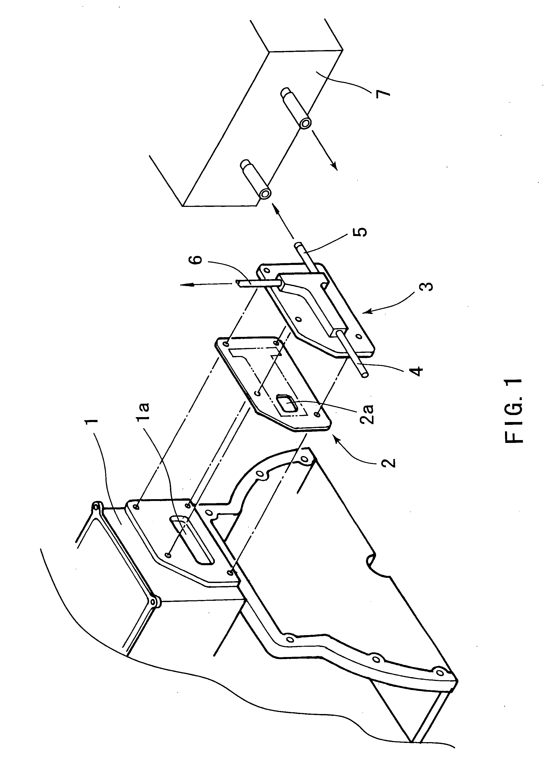
[0020] Referring to FIG. 1, in the side surface of a cylinder head 1 is provided a coolant outlet la, to which it is possible to mount a water outlet (bubble separating means) 3 through a gasket 2. This water outlet 3 is provided with a radiator connector 4 for feeding coolant to a radiator (not shown), and with a heater connector 5 for feeding coolant to a heater core 7, and further with a throttle chamber connector 6 for feeding coolant to a throttle chamber (not shown).
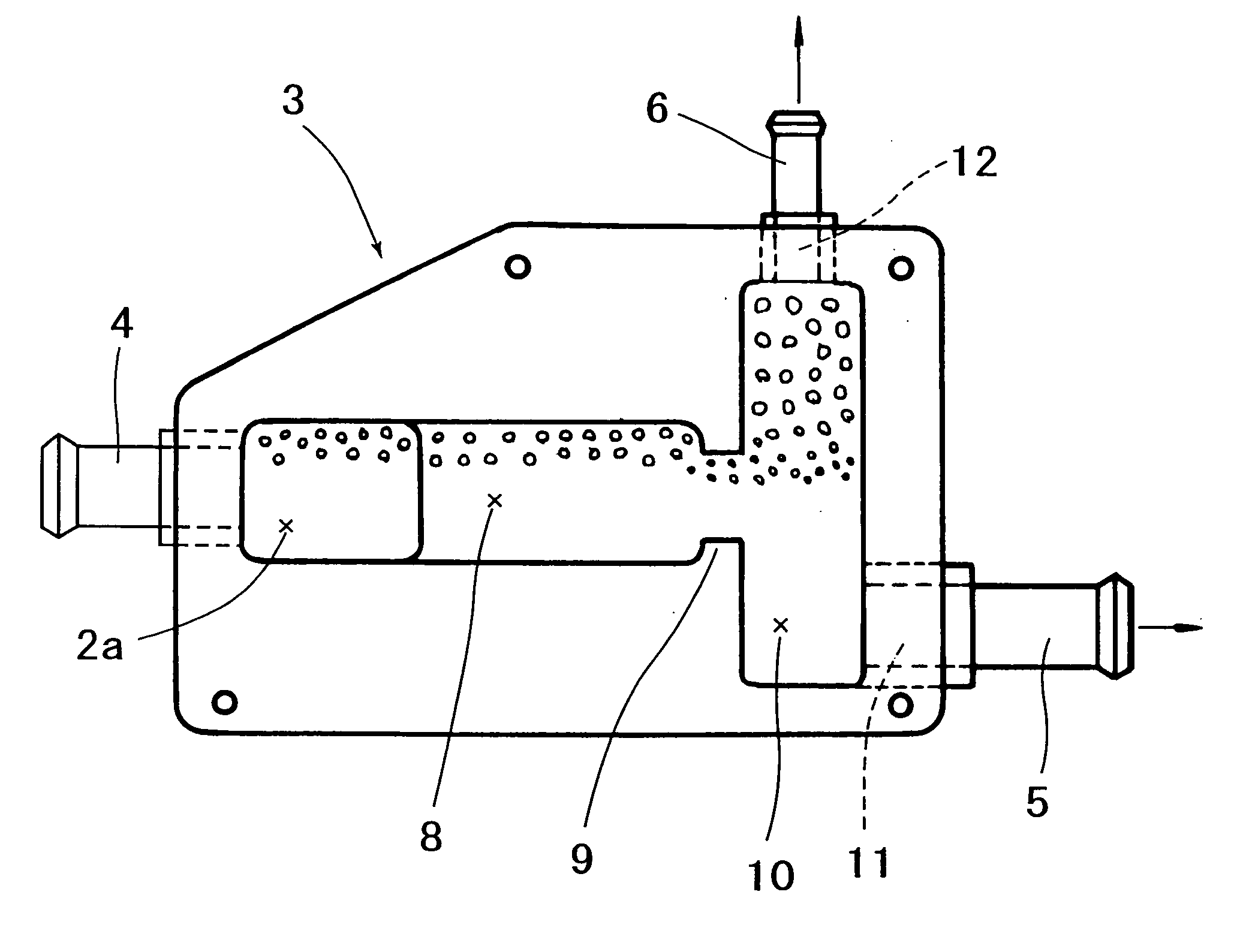
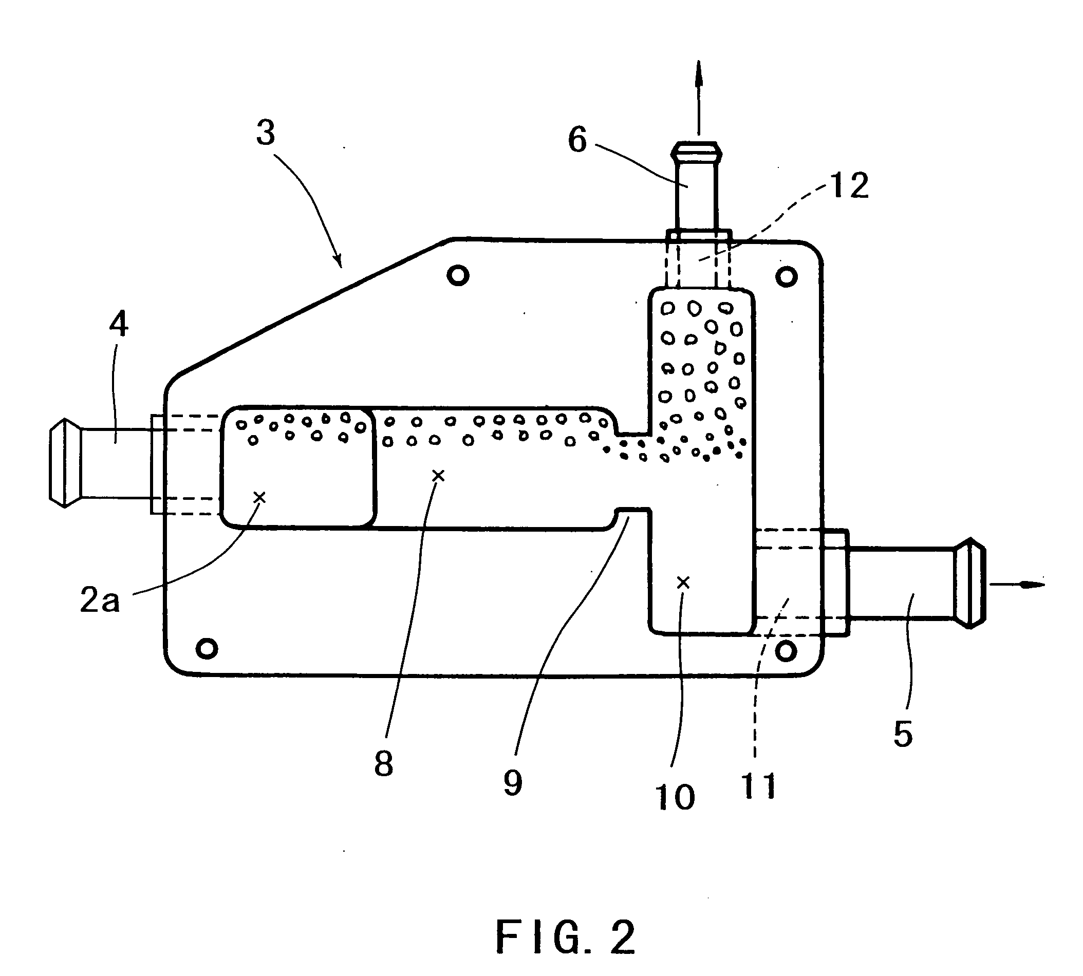
[0021] Referring to FIG. 2, inside the water outlet 3 is formed a receiving chamber 8 extending laterally from the position aligned with the outlet la (FIG. 1) and with an inlet 2a opened in the gasket 2. In the right end (as illustrated) of this receiving chamber 8 is formed a communicating portion 9 with a smaller cross section than that of the chamber 8. Further in the right end (as...
PUM
| Property | Measurement | Unit |
|---|---|---|
| Area | aaaaa | aaaaa |
| Efficiency | aaaaa | aaaaa |
| Specific gravity | aaaaa | aaaaa |
Abstract
Description
Claims
Application Information