Field emission device and driving method thereof

Active Publication Date: 2010-09-30
ELECTRONICS & TELECOMM RES INST
View PDF7 Cites 5 Cited by
  • Summary
  • Abstract
  • Description
  • Claims
  • Application Information

AI Technical Summary

Benefits of technology

[0010]The present invention is directed to providing a field emission device capable of decreasin

Problems solved by technology

However, such pulse driving produces noise due to vibration of the metal

Method used


Image

  • Field emission device and driving method thereof
  • Field emission device and driving method thereof
  • Field emission device and driving method thereof

Examples


Example

[0035]The present invention will be described more fully hereinafter with reference to the accompanying drawings, in which exemplary embodiments of the invention are shown. This invention may, however, be embodied in different forms and should not be construed as limited to the embodiments set forth herein. In the drawings, portions irrelevant to a description of the present invention are omitted for clarity, and like reference numerals denote like elements.

[0036]Throughout the specification, it will be understood that when a portion “comprises” an element, it is not intended to exclude other elements but can further include other elements.

[0037]Hereinafter, exemplary embodiments of the present invention will be is described in detail with reference to the accompanying drawings.

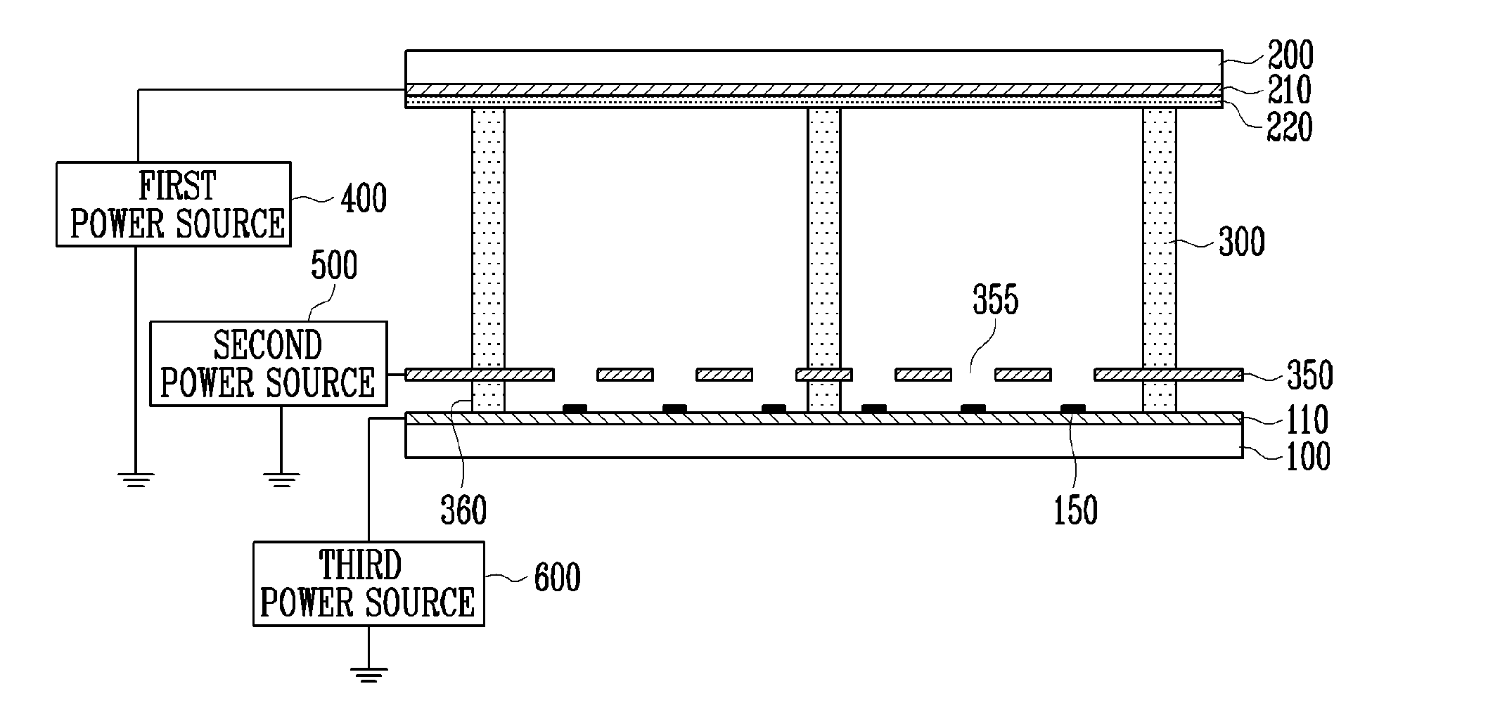
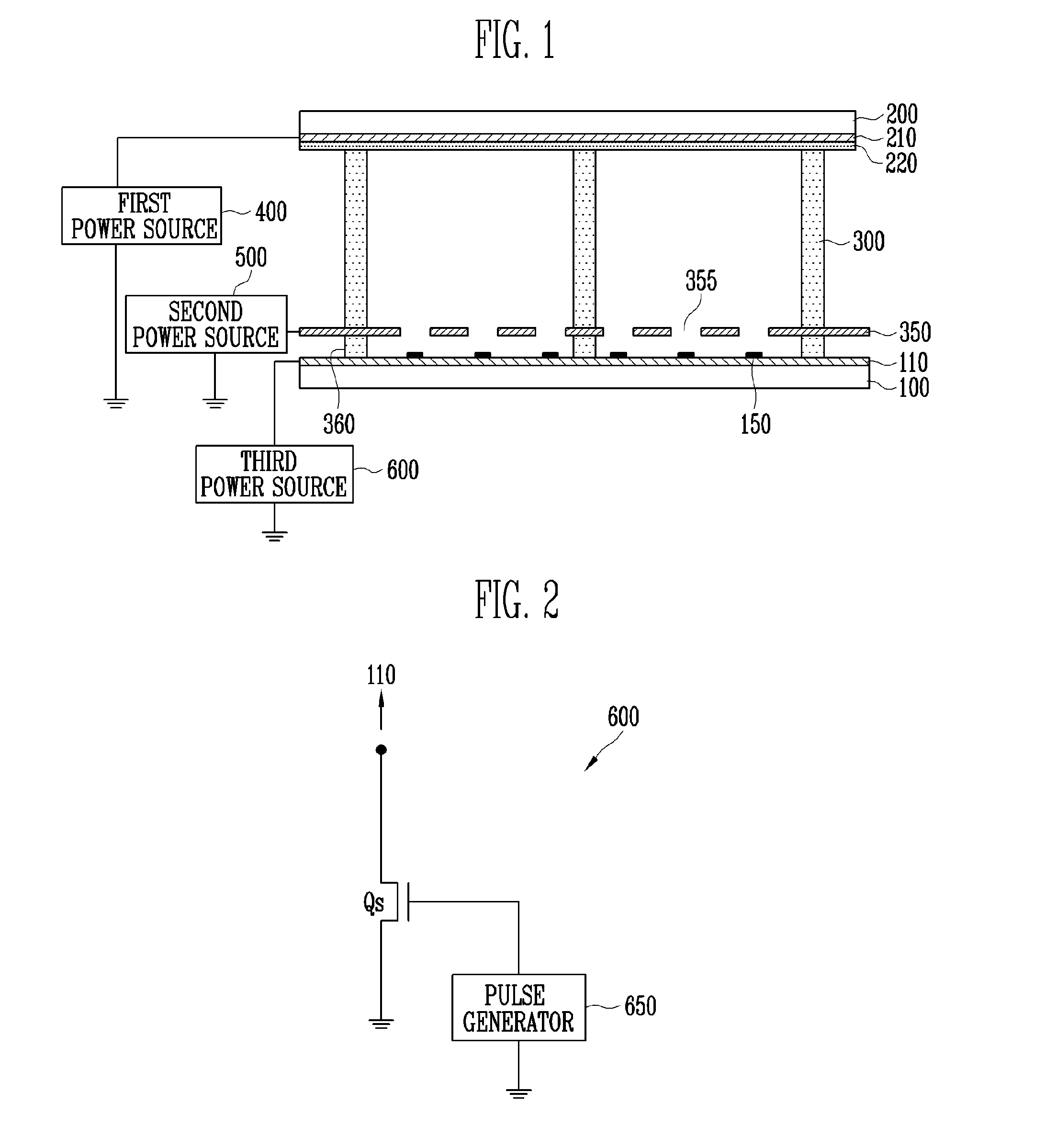
[0038]FIG. 1 is a cross sectional view of a field emission device according to a first exemplary embodiment of the present invention, and FIG. 2 is a diagram of a third power source shown in FIG. 1.

[0039]Refe...


PUM


Abstract

Provided is a pulse drive-type field emission device. The pulse drive-type field emission device includes anode and cathode substrates that are spaced apart from and face each other, a cathode electrode formed on the cathode substrate, and a field emitter formed on the cathode electrode. The pulse drive-type field emission device further includes a metal mesh-type gate electrode having an opening through which electrons emitted from the field emitter pass and a power source which applies a compensated pulse wave power to the gate electrode or the cathode electrode to compensate for vibration of the gate electrode. Thus, noise from the metal mesh can be prevented without additional fabrication processes by modifying a waveform in pulse driving.

Description

[0001]This application claims the benefit of Korean Patent Application No. 10-2009-0026868, filed Mar. 30, 2009, the contents of which are hereby incorporated herein by reference in their entirety.BACKGROUND OF THE INVENTION[0002]1. Field of the Invention[0003]The present invention relates to a field emission device, and more particularly, to a field emission device capable of decreasing noise made in a metal mesh-type gate electrode thereof and a driving method thereof.[0004]2. Description of Related Art[0005]A field emission device includes a gate electrode for inducing electrons from a field emitter and concentrating emitted electrons to a particular region of an anode.[0006]The gate electrode may be formed as a metal mesh-type electrode whose both ends are fixed to a cathode substrate.[0007]In general, a field emission device and a field emission display require pulse driving to guarantee durability of a field emitter or represent dynamic gradation.[0008]However, such pulse driv...

Claims


Application Information

Patent Timeline
IPC IPC(8): H05B41/16
CPCG09G3/22G09G2310/0275H01J2329/4695G09G2310/067H01J31/127G09G2310/066H01J1/30
Inventor JEONG, JIN WOOSONG, YOON HO
Owner ELECTRONICS & TELECOMM RES INST
Why Eureka
Try Eureka