Paper feeding device

a technology of paper feeding and paper clips, which is applied in the direction of thin material processing, article separation, printing, etc., can solve the problems of reducing the efficiency of paper feeding, requiring a certain amount of time, and not fundamentally eliminating the variation of the leading edge position

Active Publication Date: 2016-06-02
RISO KAGAKU CORP
View PDF1 Cites 10 Cited by
  • Summary
  • Abstract
  • Description
  • Claims
  • Application Information

AI Technical Summary

Benefits of technology

[0025]When sheets different in paper type are sent out from the paper feed tray, the configuration described above can brake the paper feeding motor to stop the paper feeding motor in accordance with the timing of the trailing edge of the sheet passing the paper feeding roller, by performing the braking control according to the content corresponding to the paper type of each sheet.

Problems solved by technology

Stopping the motor for the paper feeding roller by the deceleration control requires a certain amount of time.
However, this technique does not fundamentally eliminate variation in the leading edge position among the sheets sent out from the paper feed tray.

Method used


Image

  • Paper feeding device
  • Paper feeding device
  • Paper feeding device

Examples


Embodiment Construction

[0037]In the following detailed description, for purposes of explanation, numerous specific details are set forth in order to provide a thorough understanding of the disclosed embodiments. It will be apparent, however, that one or more embodiments may be practiced without these specific details. In other instances, well-known structures and devices are schematically shown in order to simplify the drawing.

[0038]Description will be hereinbelow provided for embodiments of the present invention by referring to the drawings. It should be noted that the same or similar parts and components throughout the drawings will be denoted by the same or similar reference signs, and that descriptions for such parts and components will be omitted or simplified. In addition, it should be noted that the drawings are schematic and therefore different from the actual ones.

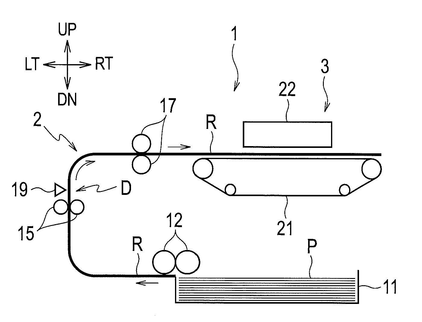
[0039]FIG. 1 is an explanatory diagram illustrating a schematic configuration of a printer including a paper feeding device in one emb...


PUM


Abstract

A braking content determiner determines a content of braking control on a rotating operation such that rotation of a paper feeding motor stops within a time required for stopping from a time point of detection of a sheet by a sheet sensor to a time point of passing of a trailing edge of the sheet through a paper feeding roller, the time required for stopping being determined based on a length of the sheet in a sheet conveying direction, a predetermined speed of the paper feeding roller, and a distance between the paper feeding roller and the sheet sensor in a sheet conveying route. A controller performs the braking control on the rotating operation of the paper feeding motor, according to the content determined by the braking content determiner, upon or prior to the detection by the sheet sensor of the sheet sent out by the paper feeding roller.

Description

CROSS REFERENCE TO RELATED APPLICATION[0001]This application is based upon and claims the benefit of priority from the prior Japanese Patent Application No. 2014-240973, filed on Nov. 28, 2014, the entire contents of which are incorporated herein by reference.BACKGROUND[0002]1. Technical Field[0003]The disclosure relates to a paper feeding device configured to feed sheets.[0004]2. Related Art[0005]A printer such as an inkjet printer or a stencil printer includes a paper feeding device configured to send out sheets from a paper feed tray and convey the sheets to a printing unit. In such a paper feeding device, a paper feeding roller sends out each sheet one by one on the paper feed tray to an intermediate conveying roller, and the intermediate conveying roller sends out the sheet to a registration roller. A leading edge of the sent-out sheet abuts on the registration roller and temporarily stops.[0006]The intermediate roller continues to send out the sheet toward the registration rol...

Claims


Application Information

Patent Timeline
Patent Type & Authority Applications(United States)
IPC IPC(8): B65H3/06B65H5/06B65H7/20B41J13/076
CPCB65H3/0669B41J13/076B65H2403/725B65H7/20B65H5/06B65H3/0638B65H2404/14B65H3/06B65H5/062B65H7/02B65H7/18B65H2511/11B65H2511/416B65H2511/514B65H2513/512B65H2701/1311B65H2513/20B65H2515/10B65H2220/01B65H2220/02B65H2220/11B65H2403/00
Inventor INOUE, HIDEAKI
Owner RISO KAGAKU CORP
Why Eureka
Try Eureka