Ion implant dose control

a technology of ion implants and substrates, applied in the direction of irradiation devices, table equipments, nuclear engineering, etc., can solve the problems of high beam current measurement errors, time-consuming and expensive failure to achieve such standards, and achieve the effect of optimising pump down time and eliminating quadrature variation

Inactive Publication Date: 2005-03-22
APPLIED MATERIALS INC
View PDF3 Cites 37 Cited by
  • Summary
  • Abstract
  • Description
  • Claims
  • Application Information

AI Technical Summary

Benefits of technology

Said ion beam generator is operated to generate a beam having orthogonal cross-sectional dimensions which are less than said diameter and the scanning apparatus is operative to scan the beam in multiple spaced lines over the wafer to form a raster, with said separating periods between said scan lines; and wherein said processor is operated: to store ionic current measurements received during separating periods at the end of selected said scan lines distributed over the wafer area; to calculate using an estimate of said pump down time constant, a corrected total beam current value from the received measurements following each of said selected scan lines to provide an array of corrected total beam current values against the positions of the respective scan lines across the wafer in the scan line spacing direction; to detect from said array, a predetermined quadrature variation of said calculated, corrected total beam current values with position across the wafer; and to calculate an improved estimate of said pump down constant which substantially eliminates said quadrature variation when used to calculate said corrected total beam current values of the array.
Optionally, the processor eliminates the quadrature variation by optimising the pump down time constant iteratively.

Problems solved by technology

Failure to achieve such standards is both time consuming and very costly due to the significantly high cost of the wafers themselves.
Collisions may also result in the state of charge of beam ions being increased, e.g. from singly to doubly charged or reduced from doubly or singly charged, and both these effects can contribute to beam current measuring errors.
A disadvantage of the method described in U.S. Pat. No. 6,297,510 is that it requires the pressure in the vacuum chamber to be measured in order to determine the pump-down time constant τ. This introduces a requirement for an additional detector capable of measuring the pressure within the vacuum chamber, and this is detrimental in terms of the complexity and expense of the ion implanter.

Method used


Image

  • Ion implant dose control
  • Ion implant dose control
  • Ion implant dose control

Examples


Embodiment Construction

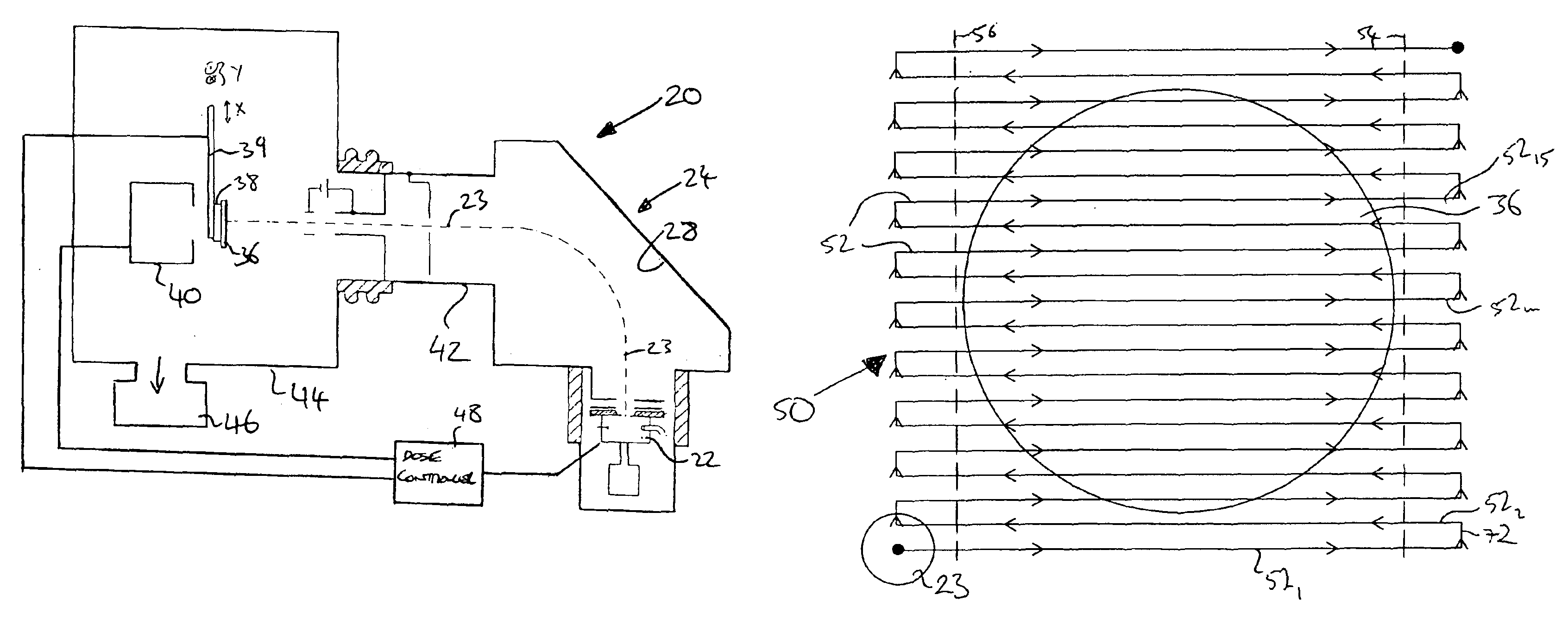
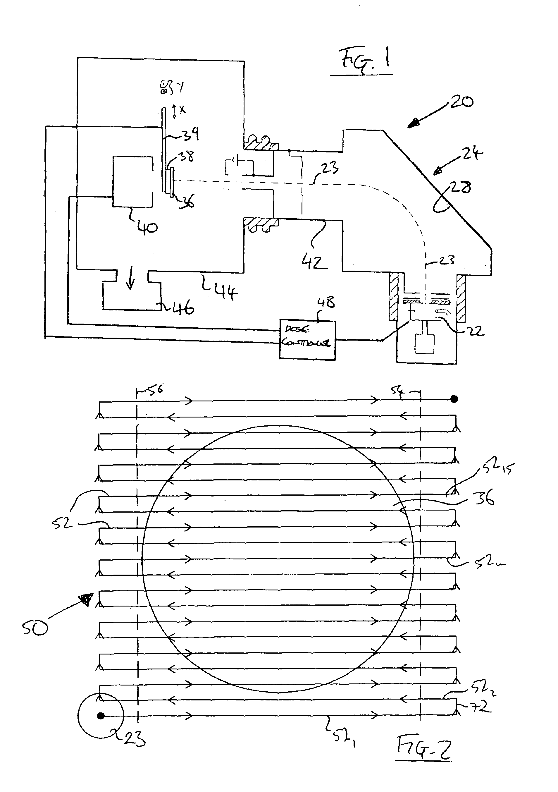
The present invention can readily be illustrated with reference to such a single wafer implant machine, such as the ion implanter 20 shown in FIG. 1. However, it should be understood that the invention may also be embodied in batch implanters of the type in which a batch of wafers mounted on a spinning wheel is processed simultaneously.

The single wafer machine of FIG. 1 comprises an ion source 22, such as a Freeman or Bernas ion source, that is supplied with a pre-cursor gas for producing an ion beam 23 to be implanted into a wafer 36. The ions generated in the ion source 22 are extracted by an extraction electrode assembly into a flight tube 24 that includes a mass-analysis arrangement 28 comprising a mass-analysing magnet and a mass-resolving slit, as is well known in the art. Upon entering the mass-analysis arrangement 28 within the flight tube 24, the electrically charged ions are deflected by the magnetic field of the mass-analysis magnet. The radius and curvature of each ion's...


PUM


Abstract

This invention is concerned with the control of implanting ions into a substrate, such as doping semiconductor wafers. The ion beam is measured to ensure waters are implanted with the correct, uniform ion dose. The incident ion beam comprises ions and neutrals, yet detectors measure only ions. The ions/neutrals ratio varies with the ion implanter's chamber pressure that in turn is known to rise and fall when the ion beam is on and off the wafer respectively, according to a characteristic time constant. This invention provides methods of correcting measured ionic currents to account for neutrals using the time constant. Initially an assumed time constant is used that is later improved by measuring the ionic current after a delay sufficient to allow the chamber pressure to recover to its base value. The time constant may also be improved by removing any quadratic variation in already determined true beam current values.

Description

FIELD OF THE INVENTIONThis invention is concerned with improvements in or relating to the control of ion dosing a substrate, such as doping semiconductor wafers.BACKGROUND OF THE INVENTIONIon implanters are commonly used in the manufacture of semiconductor products for implanting ions into semiconductor substrates to change the conductivity of the material in such substrates or in pre-defined regions thereof. Ion implanters generally comprise an ion source for generating a beam of ions, a mass analyser for selecting a particular species of ions from the ion beam and means to direct the mass-selected ion beam through a vacuum chamber onto a target substrate supported on a substrate holder.Most frequently, the ion beam cross-sectional area at the target substrate is less that the surface area of the substrate which necessitates scanning of the beam over the substrate using a one or two-dimensional scan so that the beam covers the whole surface of the substrate. Three scanning techniqu...

Claims


Application Information

Patent Timeline
Patent Type & Authority Patents(United States)
IPC IPC(8): H01L21/265H01J37/30H01L21/02H01J37/304H01J37/317
CPCH01J37/3171H01J2237/31703H01J2237/30488H01J2237/30455H01J37/304A47G19/26A47J27/04
Inventor FARLEY, MARVINSAKASE, TAKAO
Owner APPLIED MATERIALS INC
Why Eureka
Try Eureka