Dispensing valve for glue dispenser

A technology of dispensing valve and dispensing machine, which is applied to coatings, devices that apply liquid to surfaces, etc., can solve the problems of high maintenance frequency, high product failure rate, low dispensing efficiency, etc., and shorten the service life. , the effect of prolonging the downtime

Active Publication Date: 2019-04-09
深圳市特瑞吉科技有限公司
View PDF6 Cites 7 Cited by
  • Summary
  • Abstract
  • Description
  • Claims
  • Application Information

AI Technical Summary

Problems solved by technology

[0006] The invention provides a dispensing valve for a dispensing machine, the dispensing valve for a dispensing machine completely separates the cylinder and the valve body through a rubber pocket, and performs power transmission through the attractive force between the driving magnet and the driven magnet. There is no need to use sealing gaskets, which solves the problem that the thimble moves up and down to wear the sealing gaskets, resulting in gaps between the ejector pins and the sealing gaskets, requiring frequent shutdowns to replace the sealing gaskets, shortening the service life of the dispensing valve, high maintenance frequency, and prolonging the shutdown of the dispensing machine time, leading to the problem of low dispensing efficiency, and thus avoiding the high-pressure gas in the cylinder from entering the valve body through the gap between the thimble and the sealing gasket, so that the gas enters the glue liquid and forms bubbles in the glue liquid, resulting in dispensing The small amount of glue dispensed at the mouth or empty punching will seriously affect the quality of the product and cause a high defect rate of the product

Method used


Image

  • Dispensing valve for glue dispenser
  • Dispensing valve for glue dispenser
  • Dispensing valve for glue dispenser

Examples


Embodiment Construction

[0022] The following will clearly and completely describe the technical solutions in the embodiments of the present invention with reference to the accompanying drawings in the embodiments of the present invention. Obviously, the described embodiments are only some, not all, embodiments of the present invention. Based on the embodiments of the present invention, all other embodiments obtained by persons of ordinary skill in the art without making creative efforts belong to the protection scope of the present invention.

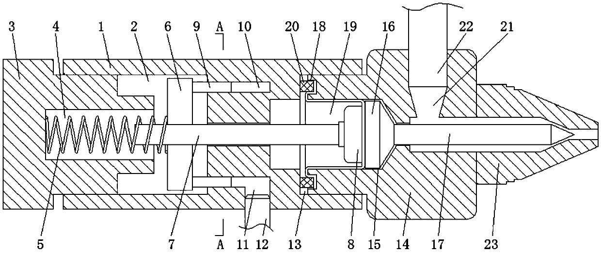
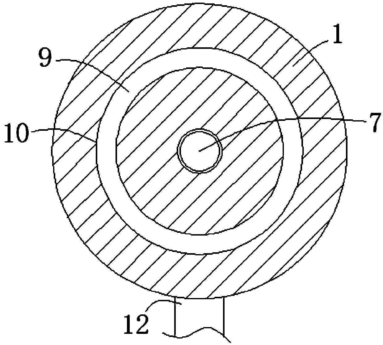
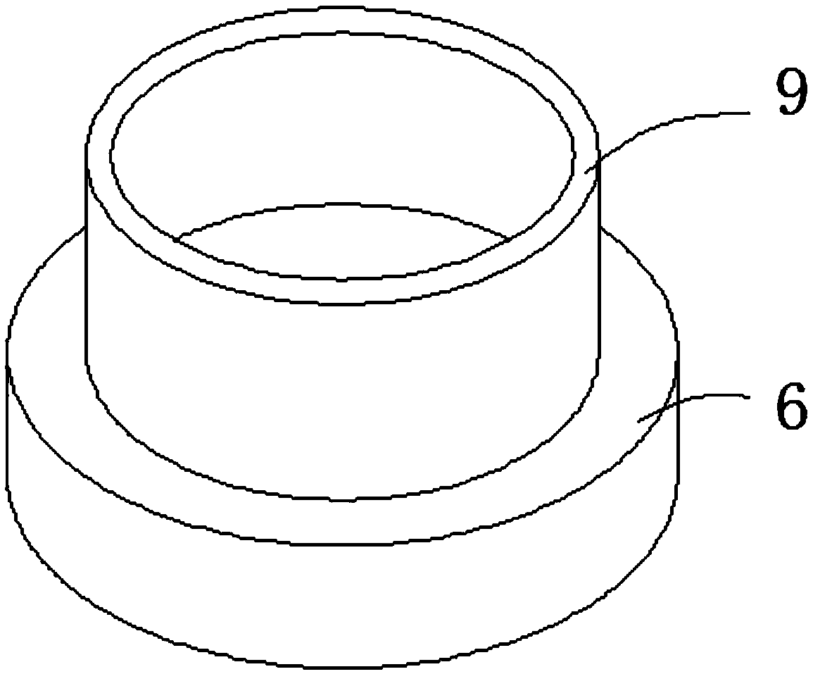
[0023] see figure 1 -4, a dispensing valve for a dispensing machine, including a cylinder 1, the left end of the cylinder 1 is provided with a buffer chamber 2, the inside of the buffer chamber 2 is provided with a stroke adjustment device 3, and the inner wall of the buffer chamber 2 It is threadedly connected with the stroke adjustment device 3, and the right end of the stroke adjustment device 3 is provided with a reset cavity 4, the inner wall of the rese...


PUM


Abstract

The invention relates to the technical field of dispensing liquid injection equipment, and discloses a dispensing valve for a glue dispenser. The dispensing valve comprises an air cylinder, the left end of the air cylinder is provided with a buffering cavity, a stroke adjusting device is arranged in the buffering cavity, the right end of the stroke adjusting device is provided with a reset cavity,and a reset spring is fixedly connected to the inner wall of the reset cavity. A valve body is sealed with a rubber pocket, high-pressure gas in the air cylinder can not enter the valve body, and kinetic energy transfer between an ejection pin and a pin head is achieved through the attractive force effect between a driving magnet and a driven magnet; and compared with the prior art, a sealing gasket does not need to be used, and the problems that in the prior art, an ejection pin vertically moves to wear a sealing gasket, gaps are generated between the ejection pin and the sealing gasket, halting is needed frequently for replacing the sealing gasket, the service life of the dispensing valve is shortened, the maintaining frequency is high, the halting time of the glue dispenser is prolonged, and then the dispensing efficiency is low are solved.

Description

technical field [0001] The invention relates to the technical field of dispensing and liquid injection equipment, in particular to a dispensing valve for a dispensing machine. Background technique [0002] The glue dispenser is an automatic device that drips and coats the fluid glue on the surface of the product or inside the product. It is mainly composed of a glue dispensing mechanism, a driving mechanism and a control system. The glue dispensing mechanism includes a pressure barrel, a dispensing valve, and a pneumatic device. Among them, the dispensing valve is composed of cylinder, piston, thimble, valve body, sealing gasket, dispensing nozzle, etc., such as Figure 4 As mentioned above, when working, the pneumatic device injects high-pressure gas into the cylinder by starting the air pressure tube, and lifts the piston upward, so that the piston moves upward with the thimble, and then the valve body is opened, and the glue flows into the valve body from the feeding pipe....

Claims


Application Information

Patent Timeline
Patent Type & Authority Applications(China)
IPC IPC(8): B05C5/02
CPCB05C5/0225
Inventor 不公告发明人
Owner 深圳市特瑞吉科技有限公司
Why Eureka
Try Eureka