
Pressure cooker component

A pressure cooker and component technology, applied in pressure cooker, cooking utensils, household appliances, etc., can solve the problems of electrical safety hazards, difficult to achieve sealing, inconvenient operation, etc., to achieve convenient operation, quick pressure release and opening, and prevent electrical safety hazards Effect

Inactive Publication Date: 2016-06-01
GREE ELECTRIC APPLIANCES INC
View PDF7 Cites 57 Cited by
  • Summary
  • Abstract
  • Description
  • Claims
  • Application Information

AI Technical Summary

Problems solved by technology

[0005] Therefore, the technical problem to be solved by the present invention is to overcome the defects of the pressure cooker in the prior art, which are inconvenient to operate, difficult to achieve sealing, and have potential electrical safety hazards, thereby providing a pressure cooker assembly

Method used


Image

  • Pressure cooker component
  • Pressure cooker component
  • Pressure cooker component

Examples


Embodiment approach 1

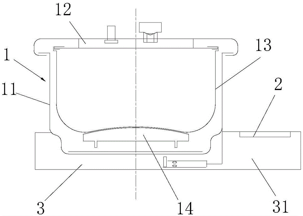
[0042]Since the display panel is not on the side, a semi-enclosed case can be used, such as image 3 , can save the raw materials of the outer pot, and can better realize artificial cooling. For example, wrapping the outer pot with a wet towel can make the pressure in the inner pot drop rapidly. Compared with exhaust and pressure relief, this pressure reduction method has no noise and can better retain the aroma of food. Electronic components generally have a temperature tolerance, and the bottom protruding part is installed with a control panel, and the controller is far away from the heat source (heating plate), so as to improve the temperature rise of electronic components and improve the service life of electronic vitality. The bottom display is adopted, so that the operation display panel faces upwards, which improves the convenience of side display operation and display reading. Since the control panel is far away from the inner pot, the water vapor in the inner pot can...

Embodiment approach 2

[0044] This display method can be combined with the traditional open flame pressure cooker, the lid of the pot is fastened with the inner pot, and the pressure limiting valve is used for pressure limiting control. After cooking, the inner pot can be taken out to cool down in water to realize quick pressure relief and opening of the lid. It not only has the convenience of electronic control operation, but also can continue cooking on an open fire in case of accidents such as power failure.

[0045] The above embodiment is that the present invention has the ability to keep the control device away from the heat source, thereby reducing the temperature rise of the control device, and preventing water vapor from entering the control device. At the same time, it also has the advantages of easy operation, display and reading.


PUM


Abstract

The invention provides a pressure cooker component. The pressure cooker component comprises a pressure cooker body (1) and a control device (2) electrically connected with the pressure cooker body (1), wherein the pressure cooker body (1) comprises an outer cooker (11) and also comprises a base (3) which is arranged under the pressure cooker body (1) to contain the pressure cooker body (1); the base (3) also comprises an extending part (31) which extends outwards along the horizontal direction from the position of the base (3) corresponding to any radial periphery of the outer cooker (11); and the control device (2) is arranged at the position of the upper surface of the extending part (31). The pressure cooker component provided by the invention has the advantages that the base is arranged at the bottom part of the pressure cooker body, the extending part extends horizontally and outwards from the position of the base corresponding to any radial periphery of the outer cooker, the control device is arranged on the position of the upper surface of the extending part and can be controlled from the upper surface of the extending part, so that the operation is convenient, completely-effective sealing for the inner part of the pressure cooker can be realized and further the potential hazards of electric safety can be prevented.

Description

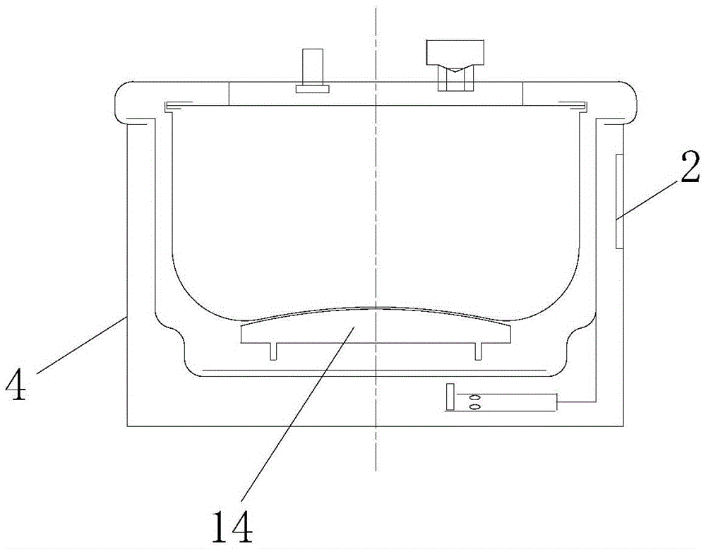
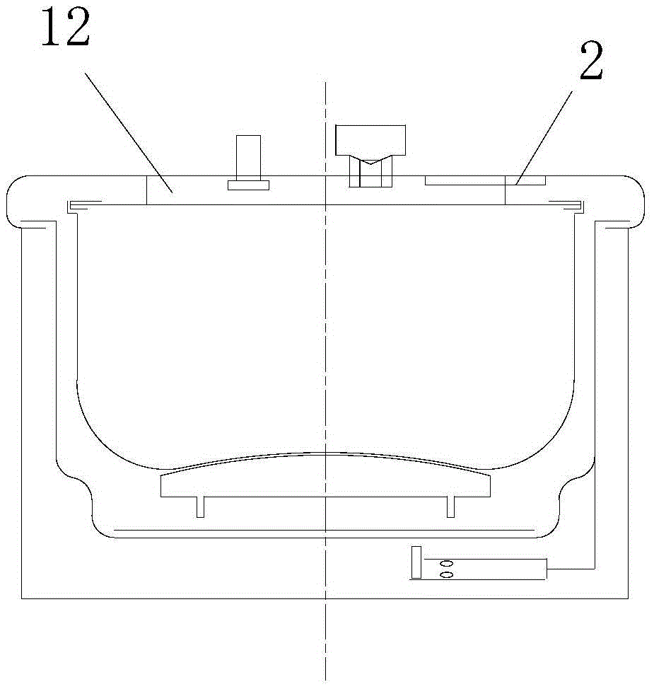
technical field [0001] The invention relates to the technical field of household appliances, in particular to a pressure cooker assembly. Background technique [0002] Along with improving constantly of people's living standard, the application of pressure cooker in people's life is also more and more extensive. [0003] At present, there are two ways to set the control device of the pressure cooker. The first way, such as figure 1 As shown, the control device 2 is installed on the side wall of the shell 4 of the pressure cooker. In this way, it is not only inconvenient to operate, but also the distance between the control device 2 and the heating device (heating plate) 14 is relatively close, so that some electronic components on the control device 2 The temperature rise of the device is higher, which reduces its service life. The second way, such as figure 2 As shown, the control device 2 is installed on the lid 12 of the pressure cooker (i.e. the top of the pressure c...

Claims


Application Information

Patent Timeline
Patent Type & Authority Applications(China)
IPC IPC(8): A47J27/08
CPCA47J27/08A47J27/0802
Inventor 张伶俐马日春胡玉新沈文君宋利郑翠翠张飞豹孔进喜冯雪张培德柏长升
Owner GREE ELECTRIC APPLIANCES INC
Learn More