Luminance correction system and method for correcting luminance of display panel

a technology of luminance correction and display panel, which is applied in the direction of instruments, static indicating devices, etc., can solve the problems of image quality reduction, and achieve the effect of improving luminance uniformity and accuracy of luminance correction

Active Publication Date: 2017-08-31
SAMSUNG DISPLAY CO LTD
View PDF2 Cites 33 Cited by
  • Summary
  • Abstract
  • Description
  • Claims
  • Application Information

AI Technical Summary

Benefits of technology

[0029]Therefore, the luminance correction system and the method for correcting the luminance of the display panel according to example embodiments may adjust downward the target luminance to secure (or increase) the grayscale correction margin, and perform the gamma correction that adju...

Problems solved by technology

Eventually, luminance spots are generated and im...

Method used


Image

  • Luminance correction system and method for correcting luminance of display panel
  • Luminance correction system and method for correcting luminance of display panel
  • Luminance correction system and method for correcting luminance of display panel

Examples


Embodiment Construction

[0041]Exemplary embodiments will be described more fully hereinafter with reference to the accompanying drawings, in which various embodiments are shown.

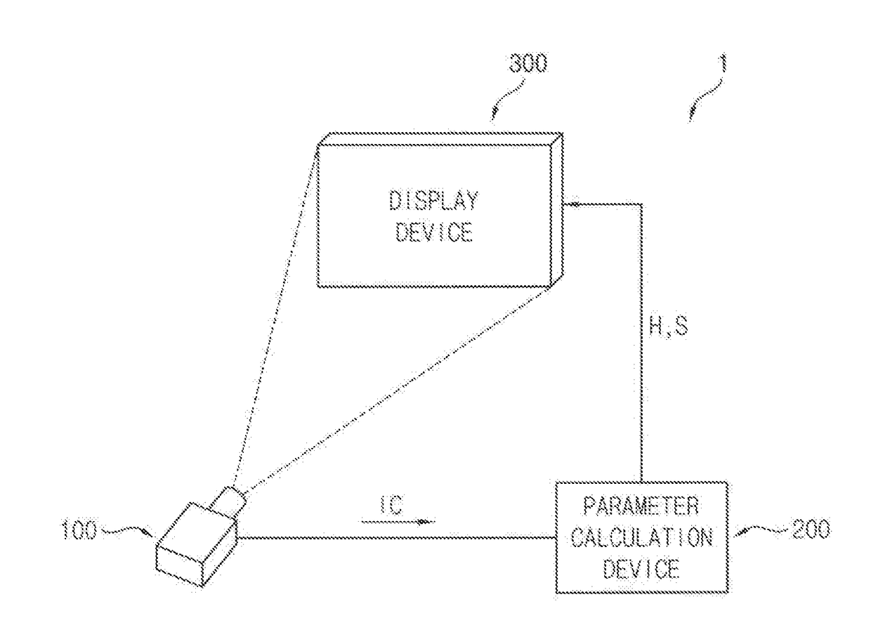
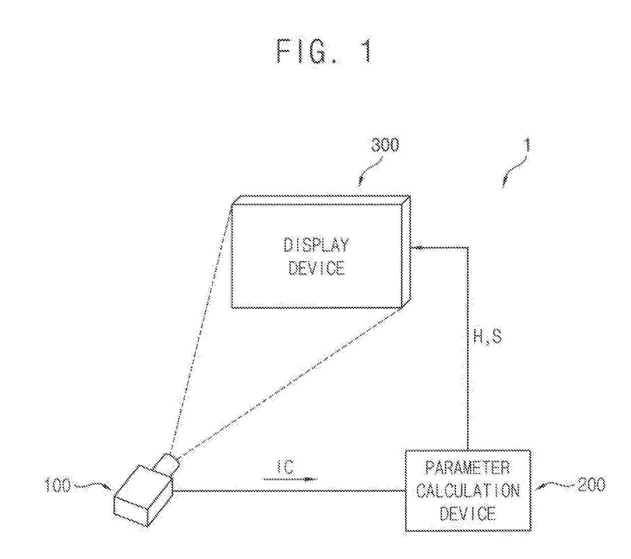
[0042]FIG. 1 is a block diagram of a luminance correction system 1 according to example embodiments.

[0043]Referring to FIG. 1, the luminance correction system 1 may include a camera device 100, also called an image pickup device 100, a parameter calculation device 200, and a display device 300.

[0044]The image pickup device 100 may pick up a test image displayed on a display panel displaying and generate pickup data IC. The image pickup device 100 may convert light signals picked up into electrical signals to generate the pickup data IC. In some embodiments, the pickup data IC may include picked up luminance information of the test image corresponding to a predetermined maximum grayscale. Since this is an example, the pickup data IC may include picked up luminance information of the test image corresponding to a specific reference gr...


PUM


Abstract

A luminance correction system includes an image pickup device configured to pick up a test image and generate pickup data, a parameter calculation device configured to calculate a first target luminance that is a maximum luminance of a reference area in a display panel and a detected maximum luminance that is a luminance of a correction target sub-pixel based on the pickup data with respect to a maximum grayscale, determine a second target luminance by correcting the first target luminance, and calculate correction parameters, and a display device including the display panel, the display device configured to compensate the input grayscale of the correction target sub-pixel to a target grayscale based on the correction parameters and generate a data voltage by adjusting upward a gamma voltage corresponding to the target grayscale.

Description

CROSS REFERENCE TO RELATED APPLICATION[0001]This application claims priority to and the benefit of Korean Patent Application No. 10-2016-0023307, filed on Feb. 26, 2016 in the Korean Intellectual Property Office (KIPO), the disclosure of which is hereby incorporated by reference herein in its entirety.BACKGROUND[0002]1. Field[0003]Example embodiments of the inventive concept relate to luminance correction systems. More particularly, example embodiments of the inventive concept relate to luminance correction systems for eliminating a luminance variation and methods for correcting luminance of display panels.[0004]2. Discussion of Related Art[0005]Recently, there have been developed various types of display devices capable of reducing the weight and volume of cathode ray tubes. Such display devices include, e.g., a liquid crystal display device (LCD), a field emission display device (FED), a plasma display panel (PDP), an organic light emitting display device (OLED), and the like.[000...

Claims


Application Information

Patent Timeline
IPC IPC(8): G09G3/20
CPCG09G3/2074G09G3/2077G09G3/2092G09G2320/0673G09G2320/029G09G2360/16G09G2320/0233G09G3/20G09G2360/147
Inventor YOO, JEONG-GEUNKIM, IN-HWANYOON, JI-HWANLEE, HYUN-HO
Owner SAMSUNG DISPLAY CO LTD
Why Eureka
Try Eureka