Power supply system and power supply apparatus

a power supply system and power supply technology, applied in the direction of power conversion systems, dc-dc conversion, electrical devices, etc., can solve the problems of a portion of noise reception and a source of noise generation on the transmission lin

Active Publication Date: 2016-06-30
MURATA MFG CO LTD
View PDF1 Cites 4 Cited by
  • Summary
  • Abstract
  • Description
  • Claims
  • Application Information

AI Technical Summary

Benefits of technology

[0006]Preferred embodiments of the present invention provide a power supply system and a power supply apparatus which do not require that a master power supply apparatus and slave power supply apparatuses be provided separately and which solve the problem of noise caused by a transmission line for a synchronization signal.
[0008]With the structure described above, without distinguishing between master and slave, synchronized parallel operation of the power supply apparatuses is realized. Since the synchronization pulse is able to be made to have a frequency lower than or equal to a switching frequency, the problem of distortion of a signal and generation / reception of noise due to the synchronization pulse bus line is alleviated.
[0010]The switching control circuit of at least one power supply apparatus of the plurality of power supply apparatuses may set a fixed delay time between a rising or falling edge of the synchronization pulse and switching of the switch device. As a result, a multiphase operation is realized.
[0012]According to various preferred embodiments of the present invention, without distinguishing between master and slave, synchronized parallel operation of the power supply apparatuses is realized. Since the synchronization pulse is able to be made to have a frequency lower than or equal to a switching frequency, the problem of distortion of a signal and generation / reception of noise due to the synchronization pulse bus line is alleviated.

Problems solved by technology

Since a synchronization signal for synchronizing the timings of switching operations and frequencies has a high frequency, wiring of a transmission line for the synchronization signal makes the transmission line a source of noise generation and a portion of noise reception.

Method used


Image

  • Power supply system and power supply apparatus
  • Power supply system and power supply apparatus
  • Power supply system and power supply apparatus

Examples


first preferred embodiment

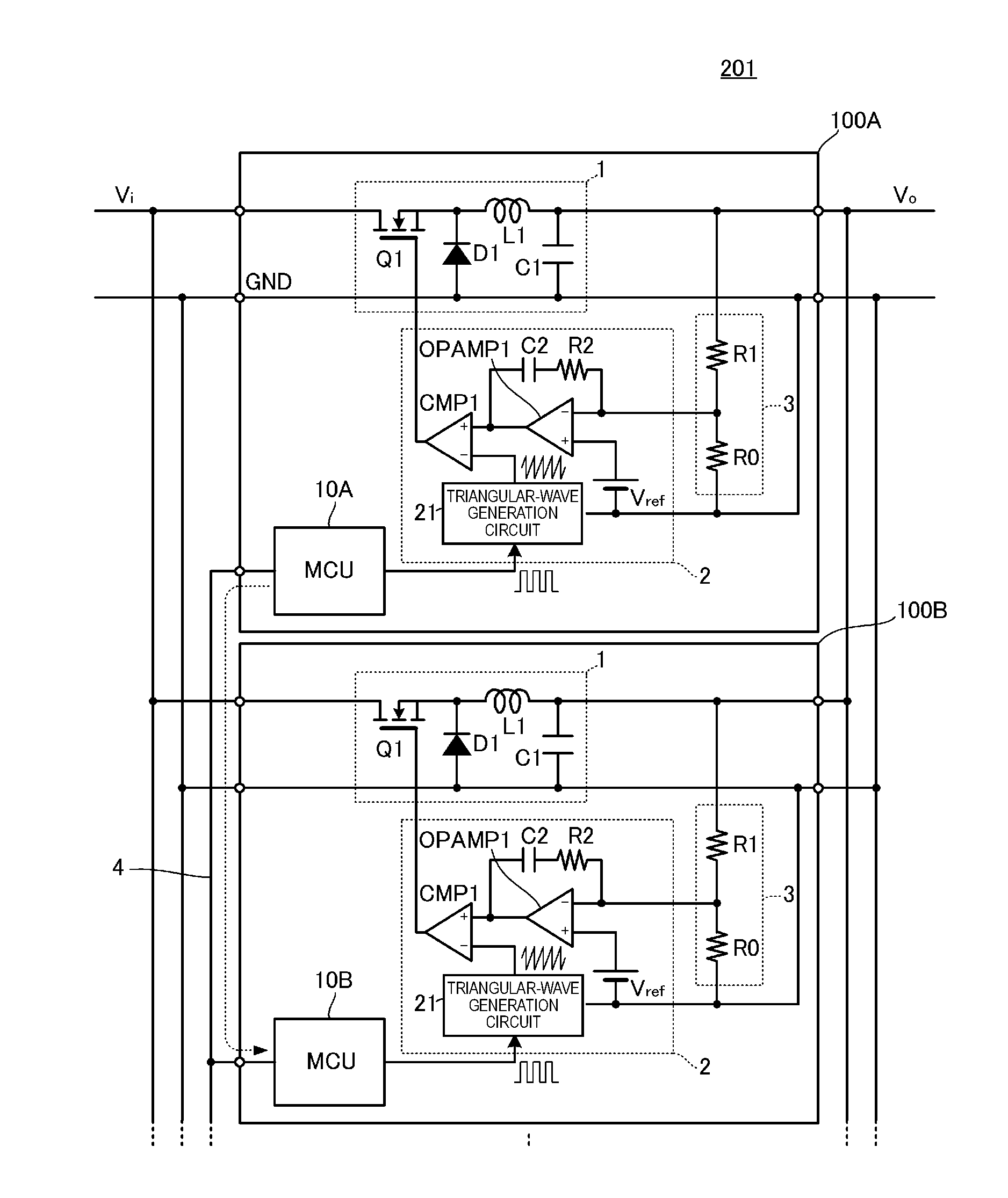
[0023]FIG. 1 is a circuit diagram of a power supply system according to a first preferred embodiment of the present invention. This power supply system 201 includes a plurality of power supply apparatuses (hereinafter, also simply called “apparatuses”) 100A, 100B, . . . and the inputs and outputs thereof are respectively connected in parallel with one another. In FIG. 1, illustration of the third apparatus and subsequent apparatuses are omitted. The apparatuses 100A, 100B, . . . basically have the same configuration.

[0024]When the apparatus 100A is taken as an example, the apparatus 100A includes a converter 1, a PWM controller 2, a controller 10A, and an output voltage detection circuit 3. The converter 1 includes a switch device Q1, a diode D1, an inductor L1, and a capacitor C1, which define a non-insulating step-down converter circuit. The PWM controller 2 includes an error amplifier OPAMP1, a PWM comparator CMP1, and a triangular-wave generation circuit 21. The PWM controller 2...

second preferred embodiment

[0050]In a second preferred embodiment of the present invention, when a first synchronization pulse generator has been synchronized with a synchronization pulse output from a second synchronization pulse generator of another power supply apparatus, the synchronization pulse generation cycle of the first synchronization pulse generator is set to be longer than the cycle of the synchronization pulse with which synchronization has been performed. The circuit configuration of the power supply system according to the second preferred embodiment is the same as the one illustrated in FIG. 1.

[0051]FIG. 5 is a waveform diagram illustrating signals generated by the synchronization pulse generators and the synchronization PWM generators. As in the example illustrated in this figure, when the cycle of a synchronization pulse generated by a synchronization pulse generator varies with the power supply apparatus, synchronization pulse generators are synchronized with one another by a synchronizati...

third preferred embodiment

[0055]FIG. 6 is a circuit diagram of a power supply system according to a third preferred embodiment of the present invention. This power supply system 202 includes two apparatuses 100A and 100B, and the inputs and outputs thereof are respectively connected in parallel with each other. The basic configuration of these two apparatuses 100A and 100B is the same as that of the apparatuses 100A and 100B illustrated in FIG. 1, except for the operation of the controller which operates as a slave differently.

[0056]FIG. 7 is a waveform diagram illustrating the operation of the power supply system according to the third preferred embodiment. The waveform of a synchronization-PWM-b signal generated by the synchronization PWM generator of the controller 10B is different from that of the example illustrated in FIG. 3. In the present example, the synchronization-PWM-b signal generated by the synchronization PWM generator 11 in the controller 10B or the like operating as a slave rises with a fixe...


PUM


Abstract

A power supply system includes a plurality of power supply apparatuses whose inputs and outputs are respectively connected in parallel with one another. The output of each of the plurality of power supply apparatuses is wired-OR connected to a synchronization pulse bus line in an open collector structure or an open drain structure. The plurality of power supply apparatuses each include a synchronization pulse generator generating a synchronization pulse for synchronization of a switching cycle, and a switching control circuit, connected to the synchronization pulse bus line, performing switching control of a switch device in synchronization with a signal of the synchronization pulse bus line. There is no distinction between a master power supply apparatus and a slave power supply apparatus in the plurality of power supply apparatuses. Further, generation of noise due to a transmission line for a synchronization signal is avoided.

Description

BACKGROUND OF THE INVENTION[0001]1. Field of the Invention[0002]The present invention relates to a power supply system including a plurality of power supply apparatuses whose inputs and outputs are respectively connected in parallel with one another.[0003]2. Description of the Related Art[0004]A power supply system in which a plurality of power supply apparatuses are connected in parallel is used to realize a high-output and a redundant operation. When a plurality of power supply apparatuses are used, in order to suppress an interference phenomenon (switching beat) due to the operations of the plurality of switching operations, the switching operations of the power apparatuses need to be synchronized with one another. Japanese Unexamined Patent Application Publication No. 9-163728, for example, discloses a configuration in which a slave side receives a synchronization signal from a master side to synchronize the operation timings and frequencies of the switching operations of switch...

Claims


Application Information

Patent Timeline
Patent Type & Authority Applications(United States)
IPC IPC(8): H02J1/00
CPCH02J1/00H02M3/1584H02J1/102H02J1/06
Inventor UNO, YOSHIYUKI
Owner MURATA MFG CO LTD
Why Eureka
Try Eureka