Motor

Inactive Publication Date: 2016-06-30
NIDEC CORP
View PDF5 Cites 10 Cited by
  • Summary
  • Abstract
  • Description
  • Claims
  • Application Information

AI Technical Summary

Benefits of technology

[0009]By employing the aforementioned configuration, the first ring and the second ring can interconnect the pillars at the positions spaced apart in the up-down direction. It is therefore possible to secure the strength of the magnet holder and to accurately perform the positioning of

Problems solved by technology

However, it is not easy to evenly dispose a plurality of magnets having a strong magnetic force along the inner circumferential surface of the rotor holder and to fix the magnets to the inner circum

Method used


Image

  • Motor
  • Motor
  • Motor

Examples


Embodiment Construction

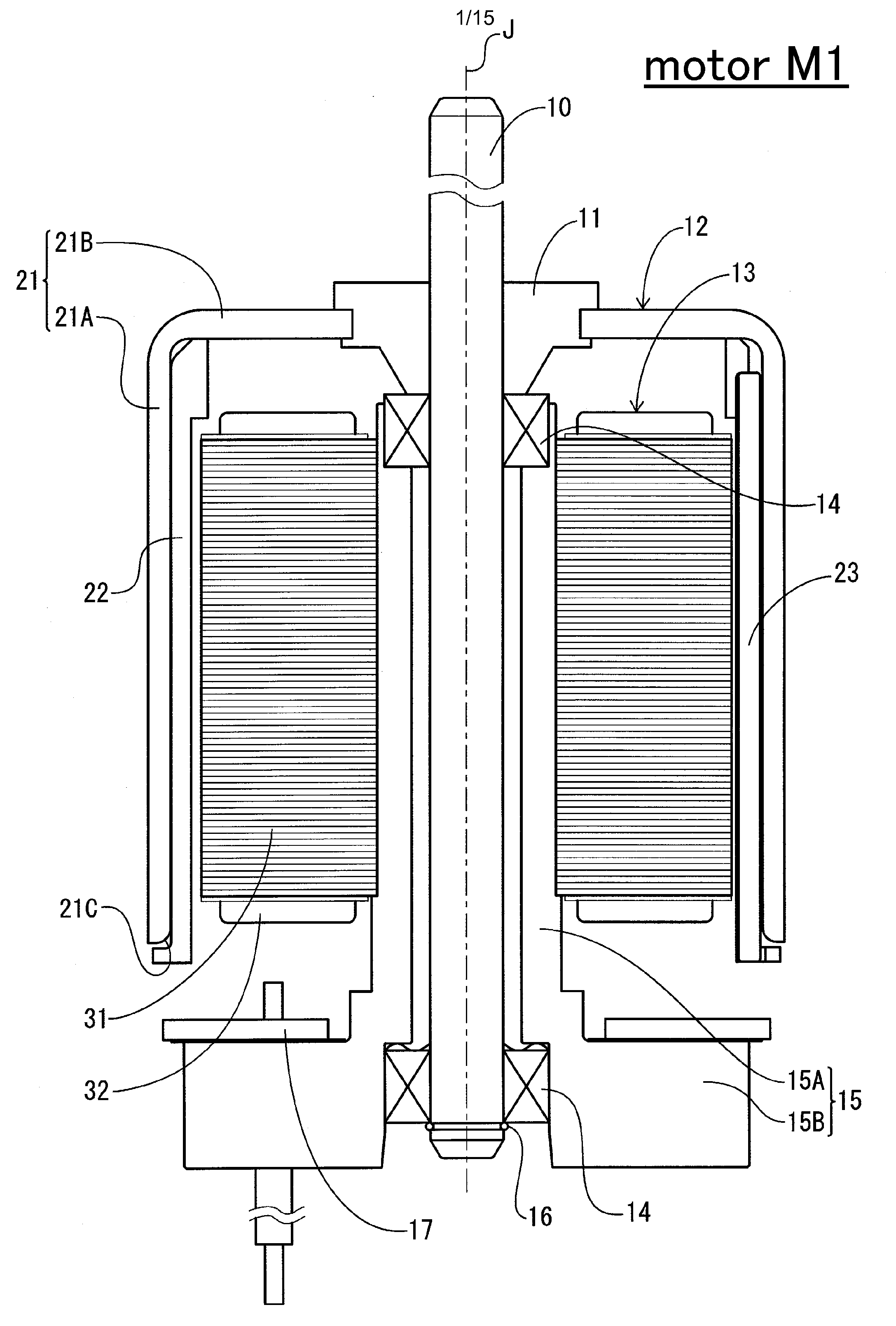
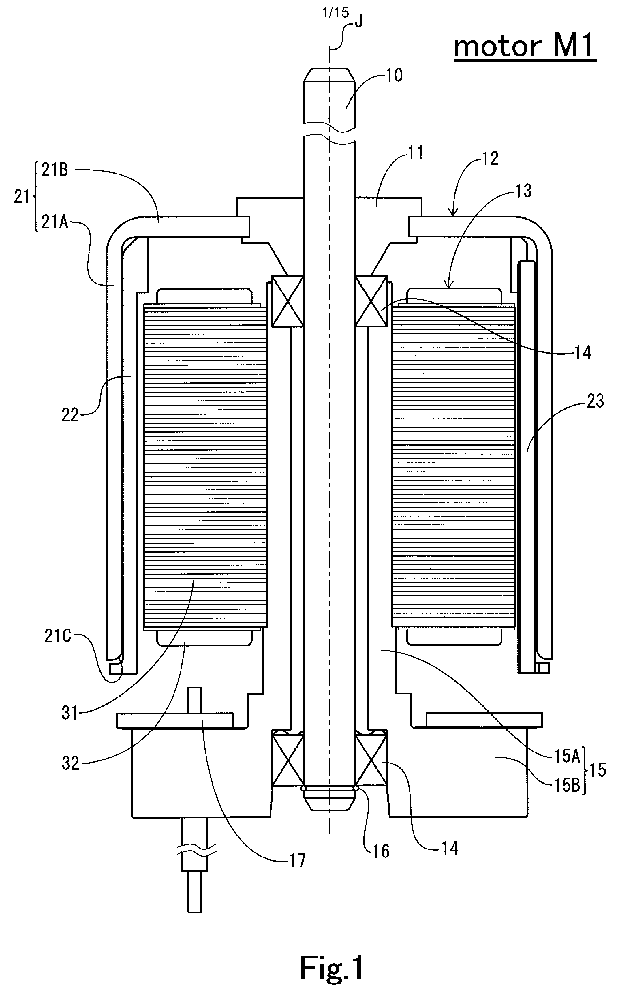
[0027]Hereinafter, illustrative embodiments of the present invention will now be described with reference to the accompanying drawings. In the subject specification, for the sake of convenience, the direction of a center axis J of a motor will be regarded as an up-down direction. However, this is not intended to limit the in-use posture of the motor according to the present invention. Furthermore, the direction of the center axis J of the motor will be simply referred to as “axial direction”. The radial direction and the circumferential direction about the center axis J will be simply referred to as “radial direction” and “circumferential direction”, respectively.

[0028]FIG. 1 is a sectional view showing one configuration example of a motor M1 according to one preferred embodiment of the present invention. The motor M1 may be used as a drive power source of a drive unit for a home appliance, office equipment, medical equipment, a motor vehicle or the like. The motor M1 preferably inc...


PUM


Abstract

A motor includes a stationary unit and a rotary unit arranged to rotate with respect to the stationary unit about a center axis extending in an up-down direction. The rotary unit includes a substantially cylindrical rotor holder, a plurality of magnets disposed radially inward of the rotor holder and arranged along a circumferential direction, and a non-magnetic magnet holder fixed to an inner circumferential surface of the rotor holder and arranged to hold the magnets. The magnet holder includes a plurality of pillars extending in the up-down direction and arranged to position the magnets in the circumferential direction, and a first ring and a second ring arranged to interconnect the pillars at positions spaced apart in the up-down direction. The first ring is positioned radially outward of the second ring, and the second ring is positioned radially inward of outer circumferential surfaces of the pillars.

Description

BACKGROUND OF THE INVENTION[0001]1. Field of the Invention[0002]The present invention relates to a motor and, more particularly, to a motor provided with a non-magnetic magnet holder for holding a plurality of magnets.[0003]2. Description of the Related Art[0004]In an outer-rotor-type brushless motor, a rotor magnet is arranged on the inner circumferential surface of a rotor holder. A cylindrical magnet is used as the rotor magnet. Instead of the cylindrical magnet, a plurality of magnets arranged in a circumferential direction may be used as the rotor magnet. However, it is not easy to evenly dispose a plurality of magnets having a strong magnetic force along the inner circumferential surface of the rotor holder and to fix the magnets to the inner circumferential surface of the rotor holder. Thus, there is conventionally known a motor provided with a magnet holder for holding a plurality of magnets arranged in a circumferential direction (see, e.g., Japanese Patent Application Publ...

Claims


Application Information

Patent Timeline
IPC IPC(8): H02K1/28H02K1/27H02K1/02
CPCH02K1/28H02K1/2706H02K1/02H02K5/163H02K11/33H02K1/2791
Inventor KANATANI, TADAYUKIKITAJI, KAZUYAARIMA, KUMIKOIKENO, SHOTA
Owner NIDEC CORP
Why Eureka
Try Eureka