Device and method for detecting force acting on tire

a technology of force acting and detecting device, which is applied in the direction of instruments, apparatus for force/torque/work measurement, ways, etc., can solve the problems of increasing costs and difficulty in reducing body siz

Inactive Publication Date: 2005-09-01
DENSO CORP
View PDF6 Cites 21 Cited by
  • Summary
  • Abstract
  • Description
  • Claims
  • Application Information

AI Technical Summary

Benefits of technology

[0006] It is an object of the present invention to provide a device or method for detecting force acting on a tire. This device or method enables downsizing of a detecting unit and calculation of torque and reaction force (or vertical force), based on outputs from sensors, while securing strength in an axial direction.

Problems solved by technology

To perform a calculation following the tire rotation speed, a high-speed processor is required, which increases costs.
Further, the calculating unit requires a given area or more, so that it is difficult to decrease the body size.

Method used


Image

  • Device and method for detecting force acting on tire
  • Device and method for detecting force acting on tire
  • Device and method for detecting force acting on tire

Examples


Embodiment Construction

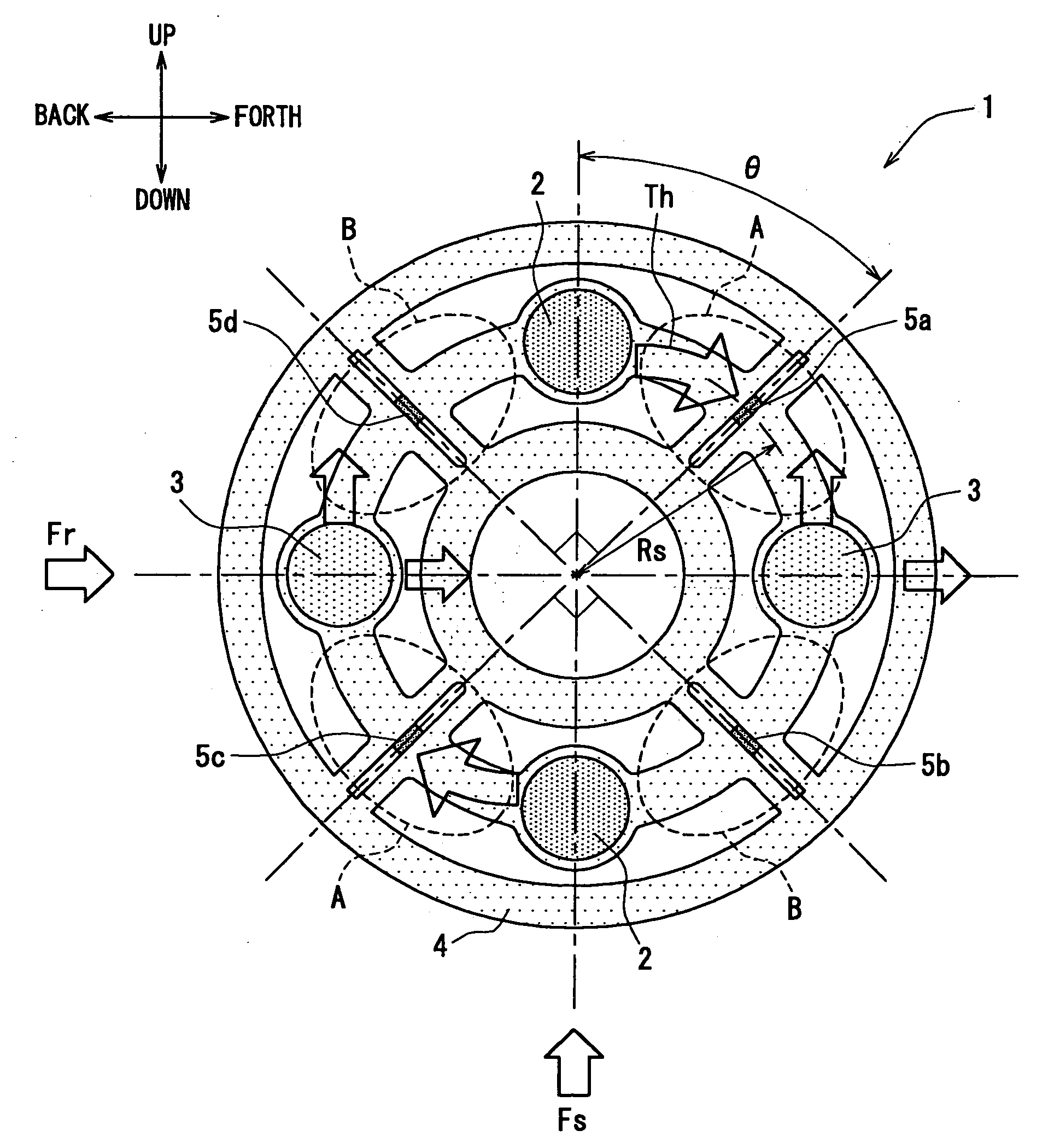
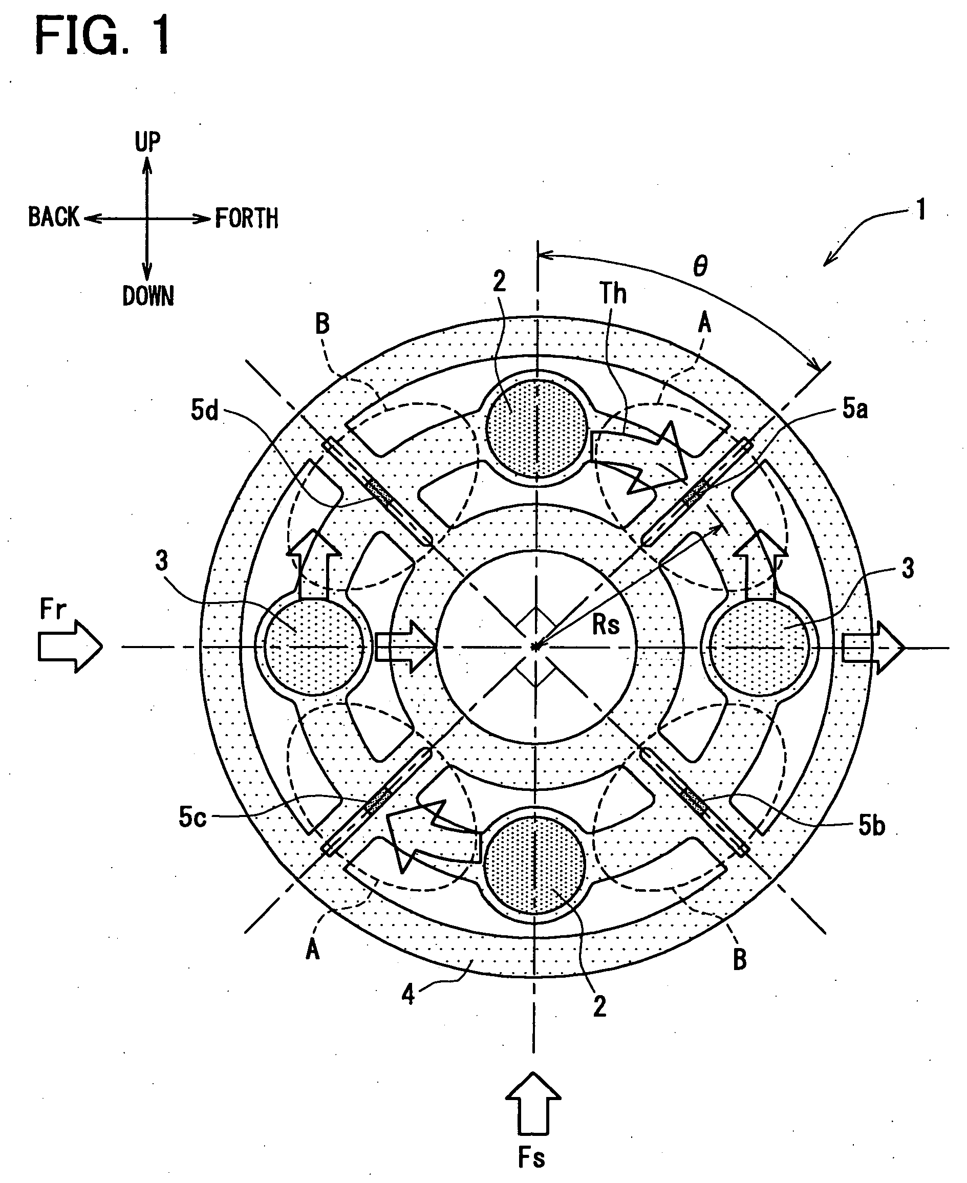
[0016] An overall structure of a tire-action-force detecting device that detects force acting on a tire according to an embodiment of the present invention is shown in FIG. 1. The device 1 includes a circular rotation body 4 with its circular center being on a rotational axis. The rotation body 4 includes linking portions 2, 3 on a circumference of a coaxial circle whose center is on the rotational axis. Further, the linking portions 2, 3 are positioned to evenly divide the circumference of the circle into four portions. Here, the linking portions 2, 3 include axle-side linking portions 2 that link with a drive shaft or an axel 10, and wheel-side linking portions 3 that link with a disk wheel 22. Each of the axle-side linking portions 2 and each of the wheel-side linking portions 3 are disposed alternately with each other on the circumference of the coaxial circle.

[0017] The axle-side linking portion 2 and the wheel-side linking portion 3 sandwich an elastically-deformable region A...


PUM

PropertyMeasurementUnit
forceaaaaaaaaaa
torqueaaaaaaaaaa
compression forceaaaaaaaaaa

Abstract

Two axle-side linking portions and two wheel-side linking portions are included in a rotation body. They are alternately arranged in four positions that are disposed, with equal intervals, along a circumference of a coaxial circle within the rotation body. Four regions located between the axle-side linking portions and the wheel-side linking portions are formed by an elastically deformable member. Further, four ceramic load sensors are arranged respectively in middle positions of the four regions along the coaxial circle. Force acting on a tire is thereby detected only from detection values by a load sensor group of the four load sensors.

Description

CROSS REFERENCE TO RELATED APPLICATIONS [0001] This application is based on and incorporates herein by reference Japanese Patent Application No. 2004-52319 filed on Feb. 26, 2004. FIELD OF THE INVENTION [0002] The present invention relates to a technology that detects force acting on a tire in a vehicle. BACKGROUND OF THE INVENTION [0003] There is proposed a tire-action-force detecting device for detecting grounding reaction force acting on a tire, for controlling an anti-lock brake system (ABS) or a traction control system. This detecting device detects a slip ratio of a tire to thereby enable calculation of a road-surface friction coefficient. Here, the calculation of the slip or the like is executed by using torque acting on a tire and a detection value such as a rotation number of the tire, as described in Patent Document 1. [0004] Patent Document 1: JP-2003-14563 A (US20030000316A1) [0005] In the above detecting device, the torque acting on a tire is detected without any proble...

Claims


Application Information

Patent Timeline
Patent Type & Authority Applications(United States)
IPC IPC(8): G01L5/00B60T8/171G01L5/16G01L5/20
CPCG01L5/162G01L5/161
Inventor MORIKAWA, KENJI
Owner DENSO CORP
Why Eureka
Try Eureka