Gas sensor control device

a control device and sensor technology, applied in the direction of electrochemical variables, instruments, exhaust treatment, etc., can solve the problems of disadvantageous delay in the output change relative to the actual change in the air-to-fuel ratio, and possibly influence on the exhaust emissions, so as to improve the reliability of the output of the gas sensor

Active Publication Date: 2016-07-14
DENSO CORP
View PDF29 Cites 2 Cited by
  • Summary
  • Abstract
  • Description
  • Claims
  • Application Information

AI Technical Summary

Benefits of technology

[0008]It is a major objective of the present disclosure to provide a gas sensor control device that can appropriately sense an abnormality in ...

Problems solved by technology

In this type of gas sensor, when the air-to-fuel ratio of the exhaust gas changes between rich and lean, a change in the sensor output may be disadvantageously delayed relative to an actual change in the air-to-fu...

Method used


Image

  • Gas sensor control device
  • Gas sensor control device
  • Gas sensor control device

Examples


Embodiment Construction

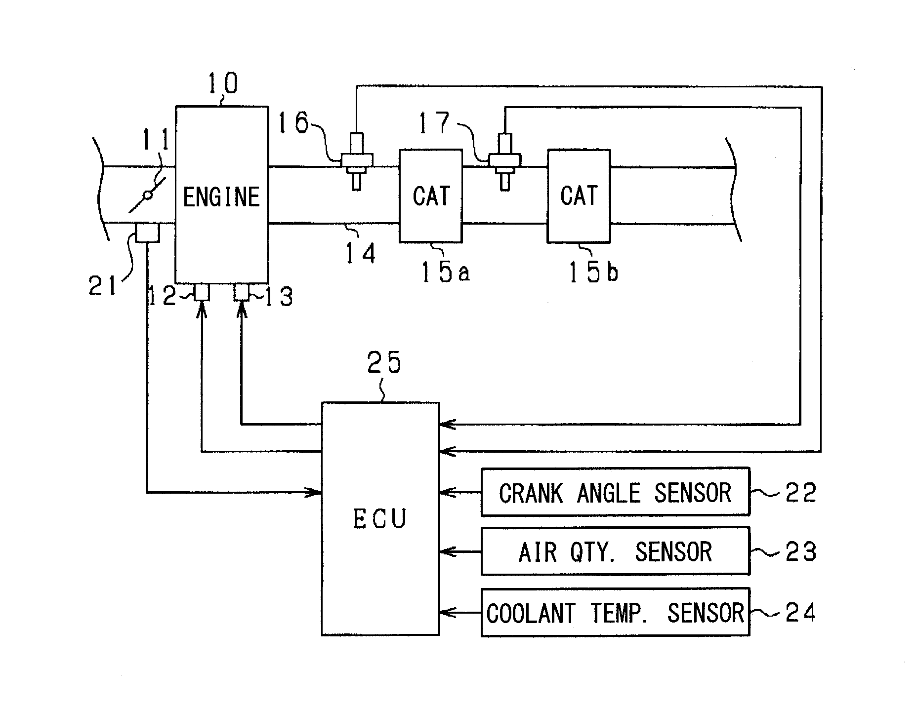
[0023]An embodiment of the present disclosure will be described with reference to the accompanying drawings. In the present embodiment, a gas sensor, which is provided in an exhaust conduit of an engine (internal combustion engine) of a vehicle, is used, and there will be described an engine control system, which executes various control operations of the engine based on an output of the gas sensor. In the control system, an electronic control unit (hereinafter referred to as an ECU) is used to execute, for example, a control operation of a fuel injection quantity and a control operation of ignition timing. FIG. 1 is a diagram that schematically shows an entire structure of the system.

[0024]In FIG. 1, the engine 10 is, for example, a gasoline engine and has an electronically controlled throttle valve 11, fuel injection valves 12, and ignition devices 13. Catalysts 15a, 15b, which serve as an exhaust gas purifying device, are installed in an exhaust conduit 14 (serving as an exhaust ...


PUM


Abstract

An O2 sensor has a sensor element, which includes a solid electrolyte layer and a pair of electrodes, while the solid electrolyte layer is interposed between the electrodes. The O2 sensor outputs an electromotive force signal in response to an air-to-fuel ratio of exhaust gas of an engine, which serves as a sensing subject. A constant current circuit, which induces a flow of a predetermined constant electric current between the pair of electrodes of a sensor element, and a current sensing arrangement, which senses a current value of an actual electric current that is conducted through the sensor element, are provided. A microcomputer determines whether an abnormality of the constant current circuit is present based on the current value of the electric current, which is sensed with the current sensing arrangement, in a case where the constant current is induced by the constant current circuit.

Description

CROSS REFERENCE TO RELATED APPLICATION[0001]The present application is based on and incorporates herein by reference Japanese Patent Application No. 2013-167128 filed on Aug. 9, 2013.TECHNICAL FIELD[0002]The present disclosure relates to a gas sensor control device.BACKGROUND ART[0003]For instance, a gas sensor, which outputs an electromotive force, is provided at a vehicle engine. In this type of gas sensor, exhaust gas, which is discharged from the engine, serves as a sensing subject of the gas sensor, and an oxygen concentration of the exhaust gas is sensed with the gas sensor. This type of gas sensor includes an electromotive force cell, which outputs an electromotive force signal that varies depending on whether the exhaust gas is rich or lean. Specifically, when an air-to-fuel ratio is rich, the electromotive force cell outputs the electromotive force signal of about 0.9 V. In contrast, when the air-to-fuel ratio is lean, the electromotive force cell outputs the electromotive ...

Claims


Application Information

Patent Timeline
IPC IPC(8): F01N11/00F01N13/00G01M15/10
CPCF01N11/007G01M15/102F01N2550/02F01N13/008F01N11/002G01N27/4065G01N33/007G01N27/409G01N27/26
Inventor MATSUOKA, MIKIYASUMUKAI, YASUONAKATA, SHINGOYAMADA, YUJI
Owner DENSO CORP
Why Eureka
Try Eureka