This helps you quickly interpret patents by identifying the three key elements:
Problems solved by technology
Method used
Benefits of technology
[0010]Even when the oil splashed up by the rocker arm provided at the side of the blow-by gas outlet is flowed with the stream of the blow-by gas along the bottom wall of the breather chamber, the stream is prevented from flowing by the peripheral wall of the oil discharging guide chamber, and therefore the oil entering amount into the blow-by gas inlet is reduced, the oil e
Problems solved by technology
However, in the conventional engine, since a blow-by gas inlet is opened on a bottom wall of the breather chamber and the bottom wall of the breather chamber is formed in a flat shape, a problem has arisen.
In the conventional engine, the oil splashed up by the rocker arm is apt to enter into the blow-by gas inlet with a stream of t
Method used
Image
Click on the blue label to locate the original text in one second.
Reading with bidirectional positioning of images and text.
Examples
first embodiment
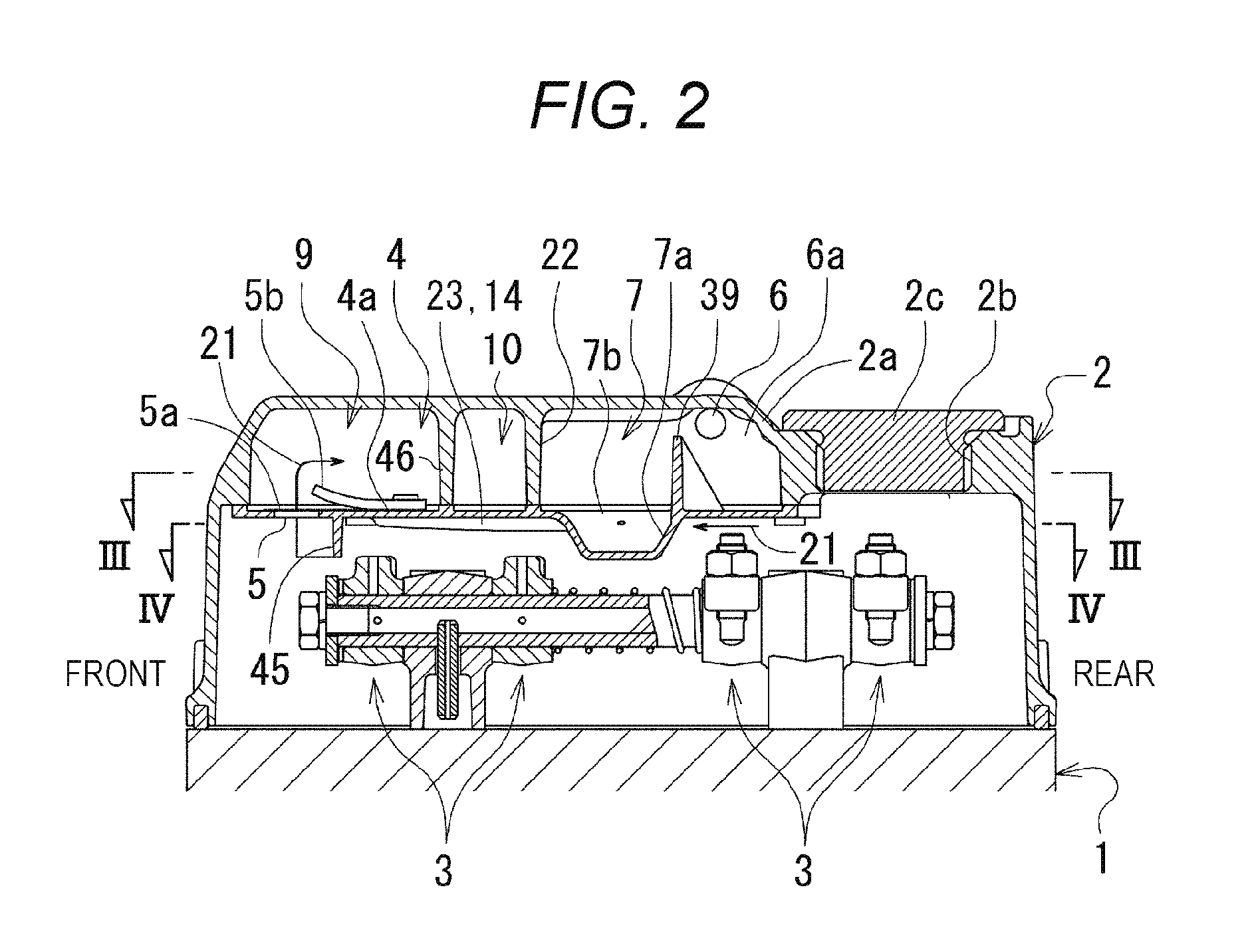
[0036]An outline of the engine is as follows.
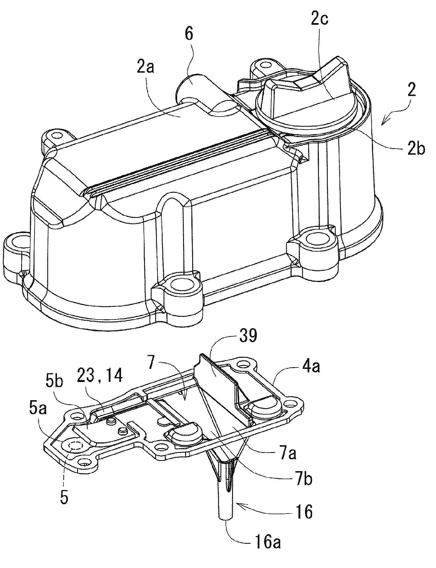
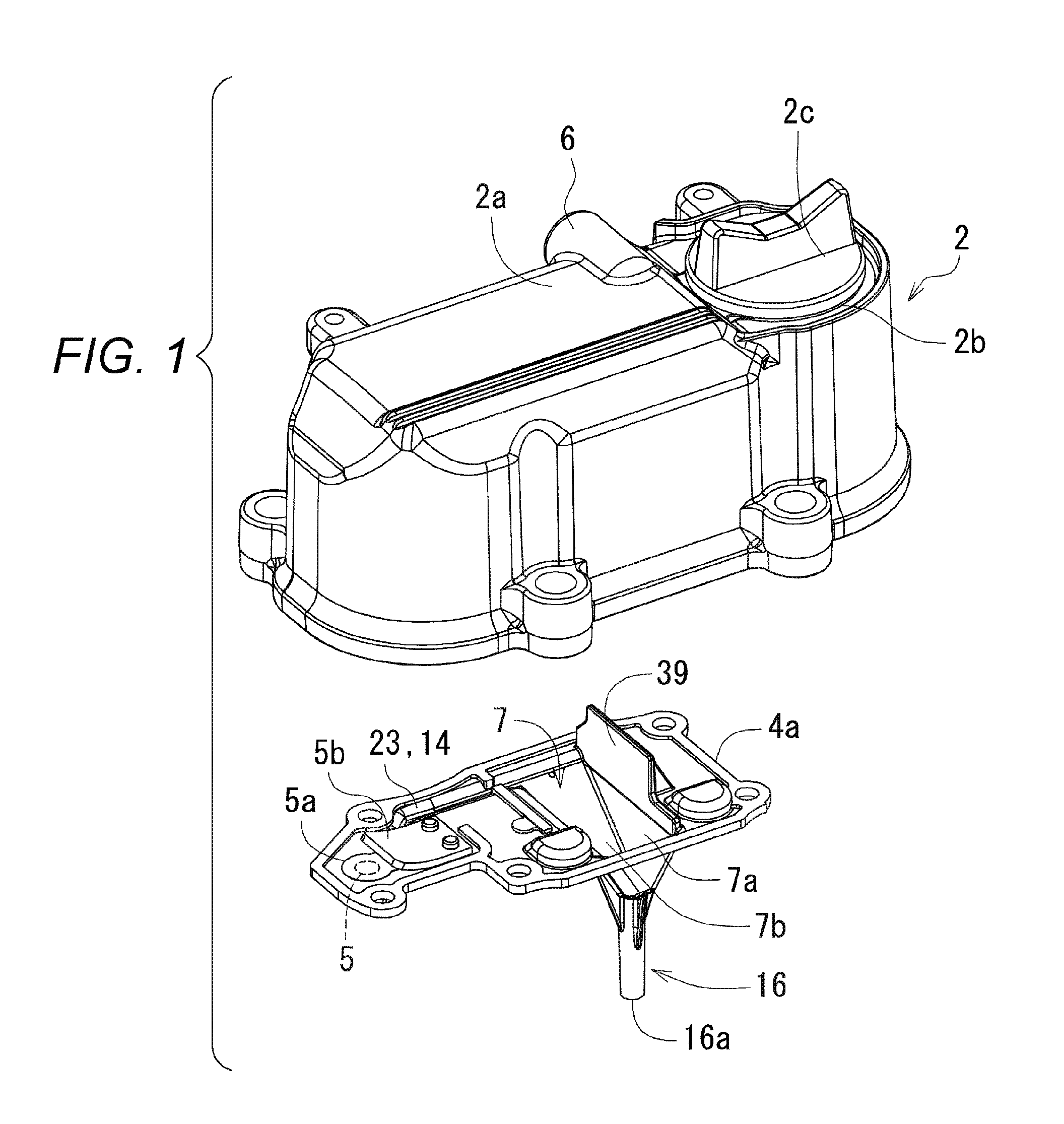
[0037]As shown in FIG. 2, a cylinder head (1) is mounted above a cylinder block (not shown), and a cylinder head cover (2) is mounted above the cylinder head (1). As a front-rear direction is defined by the installation direction of a crank shaft (not shown), its one side is defined as the front and another side is defined as the rear.
[0038]An oil pan (not shown) is mounted below the cylinder block (not shown).
[0039]A swirl chamber (not shown) is formed in the cylinder head (1), and fuel is injected into the swirl chamber (not shown) from a fuel injection pump (not shown) via a fuel injection pipe (not shown) and a fuel injection nozzle (not shown).
[0040]As shown in FIG. 7, a valve device (32) for intake air and exhaust air is housed in the cylinder head cover (2), and the valve device (32) is driven by a valve driving device (33). The valve driving device (33) is provided with a valve driving cam (not shown), a tappet (not shown), a pus...
second embodiment
[0097]Next, an engine shown in FIGS. 15 to 23 is described.
[0098]In the engine according to the second embodiment, an oil discharging guide chamber (7) has a baffle plate (8) and this configuration is different from the engine according to the first embodiment. Other configurations are similar to those in the engine according to the first embodiment.
[0099]As shown in FIGS. 16A and 16C, the oil discharging guide chamber (7) has the baffle plate (8) which receives the separated oil (18) splashed up from the pipe inlet (16c) of the oil discharging pipe (16) due to the backflow of the separated oil (18).
[0100]According to the configuration described above, even when the separated oil (18) in the oil storing part (17) is splashed up from the pipe inlet (16c) to the oil discharging guide chamber (7) due to the backflow, since the separated oil (18) is received by the baffle plate (8) and is hardly diffused in the oil discharging guide chamber (7), the separated oil (18) hardly flows out ...
PUM
Abstract
There is provided an engine capable of reducing oil consumption. The engine includes a cylinder head, a cylinder head cover mounted above the cylinder head, a rocker arm covered by the cylinder head cover, and a breather chamber provided inside the cylinder head cover. As a front-rear direction is defined by a longitudinal direction of the cylinder head cover, the breather chamber has a blow-by gas inlet at one side in the front-rear direction, a blow-by gas outlet at another side in the front-rear direction, and an oil discharging guide chamber at an intermediate part in the front-rear direction. The blow-by gas inlet is opened on a bottom wall of the breather chamber, and a peripheral wall of the oil discharging guide chamber is protruded downwardly from the bottom wall of the breather chamber toward between the rocker arm provided at a side of the blow-by gas outlet and the blow-by gas inlet.
Description
BACKGROUND OF THE INVENTION(1) Field of the Invention[0001]The present invention relates to an engine.(2) Description of Related Art[0002]However, in the conventional engine, since a blow-by gas inlet is opened on a bottom wall of the breather chamber and the bottom wall of the breather chamber is formed in a flat shape, a problem has arisen.<<Problem>> The oil Consumption Might be Increased.[0003]In the conventional engine, the oil splashed up by the rocker arm is apt to enter into the blow-by gas inlet with a stream of the blow-by gas along the bottom wall of the breather chamber, and therefore an oil amount entered into the breather chamber becomes excessive and some oil, which is not separated from the blow-by gas inside the breather chamber, is leaked from the cylinder head cover. This configuration might lead an increase of the oil consumption.SUMMARY OF THE INVENTION[0004]An object of the present invention is to provide an engine capable of reducing oil consumptio...
Claims
Application Information
Patent Timeline
Application Date:The date an application was filed.
Publication Date:The date a patent or application was officially published.
First Publication Date:The earliest publication date of a patent with the same application number.
Issue Date:Publication date of the patent grant document.
PCT Entry Date:The Entry date of PCT National Phase.
Estimated Expiry Date:The statutory expiry date of a patent right according to the Patent Law, and it is the longest term of protection that the patent right can achieve without the termination of the patent right due to other reasons(Term extension factor has been taken into account ).
Invalid Date:Actual expiry date is based on effective date or publication date of legal transaction data of invalid patent.