Two-stage oil-gas separation diesel engine breathing system

A breathing system and diesel engine technology, applied in the field of breathing system, can solve the problems of polluting environment, user cost, low efficiency, high engine oil consumption, etc., and achieve the effect of reducing oil consumption, pressure and pollution

Inactive Publication Date: 2013-12-11
东风朝阳朝柴动力有限公司
View PDF4 Cites 6 Cited by
  • Summary
  • Abstract
  • Description
  • Claims
  • Application Information

AI Technical Summary

Problems solved by technology

Facts have proved that the filtering efficiency of this method is not very high, and at the same time, the oil consumption of the engine is too high, which pollutes the environment and increases user costs.

Method used


Image

  • Two-stage oil-gas separation diesel engine breathing system
  • Two-stage oil-gas separation diesel engine breathing system
  • Two-stage oil-gas separation diesel engine breathing system

Examples


Embodiment Construction

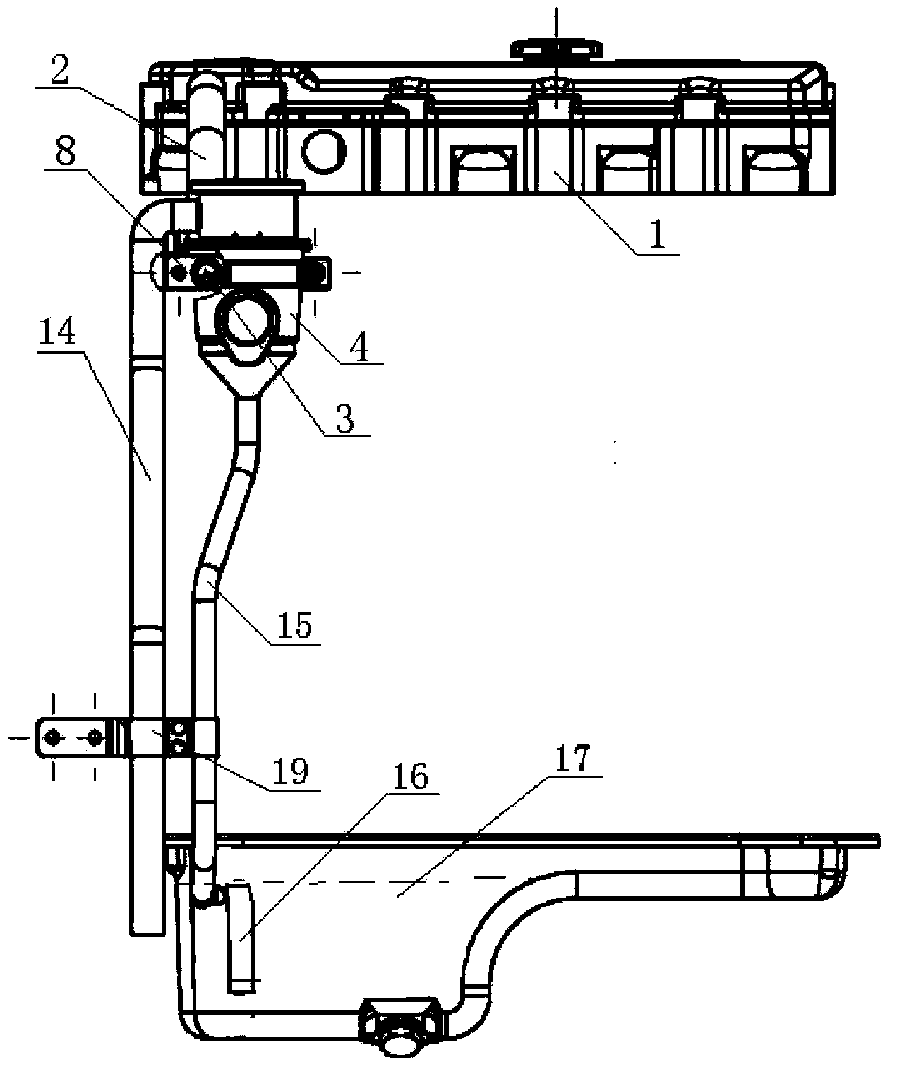
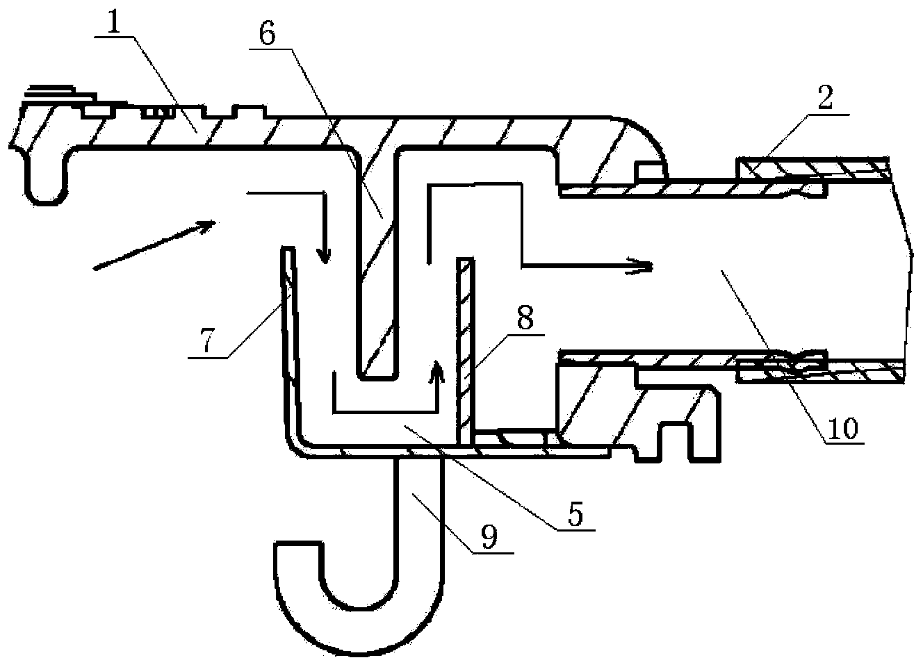
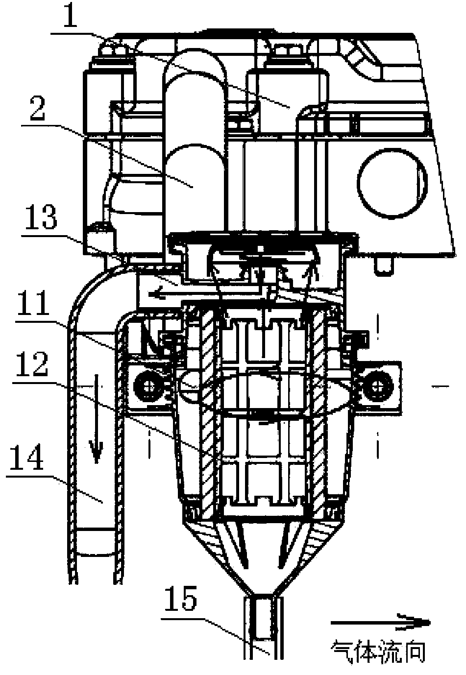
[0010] The structure and principle of the present invention will be further described below with reference to the accompanying drawings and in conjunction with the embodiments. Two-stage oil and gas separation diesel engine breathing system, its structural composition is: the rocker arm chamber cover 1 communicates with the respirator 4 through the intake pipe 2 and the channel 3, the oil and gas pre-separation chamber 5 in the rocker arm chamber cover is separated by the rocker arm cover baffle plate 6 , Front baffle 7 and rear baffle 8 are formed. The high-pressure mixed oil and gas enters the oil-air pre-separation chamber from the rocker arm chamber cover, and the oil in the mixed oil and gas is adsorbed on the baffle plate of the rocker arm cover and the front and rear baffles to complete the first oil-gas separation, and the separated oil flows back through the oil return pipe 9 Inside the cylinder head. The oil-gas mixture that still contains oil is separated for the f...


PUM


Abstract

The invention discloses a two-stage oil-gas separation diesel engine breathing system. The technical structure of the two-stage oil-gas separation diesel engine breathing system is that: high-pressure mixed oil gas enters an oil-gas pre-separation chamber in a rocker chamber cover, and is separated for the first time via a U-shaped channel consisting of three baffle plates. Engine oil is adsorbed on the baffle plates, and flows back into a cylinder cover via an oil return tube. An oil-gas mixture still containing engine oil is separated out and enters a breather through the waste gas outlet of the rocker chamber cover, the air inlet of the breather is tangential to the circular inner wall of the breather, thus the oil-gas mixture forms high-speed rotating air current in the breather, and residual engine oil and gas impurities in the oil-gas mixture are adsorbed onto a filter screen by means of centrifugal force, so that second separation is finished. Clean gas is exhausted into the atmospheric air via the air outlet of the breather and an air outlet tube. After two-stage oil-gas separation, the content of impurities and engine oil steam in waste gas is very low. A remarkable effect is achieved on reaching an emission standard and engine oil loss level while the pressure of a crankcase is lowered effectively, and pollution to the atmospheric environment is lowered effectively.

Description

technical field [0001] The invention belongs to the oil-gas separation technology of an internal combustion engine, and in particular relates to a breathing system capable of performing two-stage oil-gas separation for a diesel engine. Background technique [0002] With the enhancement of people's awareness of environmental protection, the requirements for engine emissions are getting higher and higher. It is well known that the pollution of the engine to the environment is mainly the exhaust gas discharged. When the engine is working, high-temperature and high-pressure exhaust gas such as water vapor, sulfur dioxide, engine oil vapor, and nitrogen oxides leaks into the crankcase through the gap of the piston ring. If the exhaust gas in the crankcase is not discharged in time, as the leaked gas increases, Crankcase pressure will be higher and higher. Moreover, when the temperature drops, water vapor will condense in the oil pan, making the oil thinner and forming foam at th...

Claims


Application Information

Patent Timeline
Patent Type & Authority Applications(China)
IPC IPC(8): F01M13/04
Inventor 董立明王致钊赵霄鹏孙超
Owner 东风朝阳朝柴动力有限公司
Why Eureka
Try Eureka