Main-transformation heat-dissipating device with SF6 (sulfur hexafluoride) as refrigerant medium and heat-dissipating method

A heat sink, SF6 technology, applied in refrigerators, refrigeration and liquefaction, lighting and heating equipment, etc., can solve the problems of low cooling efficiency of main transformer, large manufacturing volume and high operating cost, and achieve large equipment manufacturing volume and oil consumption. The effect of large quantity and high operating cost

Active Publication Date: 2014-05-07
STATE GRID CORP OF CHINA +5
View PDF7 Cites 6 Cited by
  • Summary
  • Abstract
  • Description
  • Claims
  • Application Information

AI Technical Summary

Problems solved by technology

Traditional main transformer cooling methods mainly include forced air cooling, natural air cooling and water cooling. Although water cooling is economical and efficient, if cooling water leaks into the main transformer in the cooling system, even if it is a small leak, It will lead to serious consequences; due to the low heat enthalpy of the air, the cooling efficiency of the main transformer is low, the manufacturing volume of the main transformer and radiator equipment is large, the oil consumption is large, the operating cost is high, and the maintenance amount is large, etc.

Method used


Image

  • Main-transformation heat-dissipating device with SF6 (sulfur hexafluoride) as refrigerant medium and heat-dissipating method
  • Main-transformation heat-dissipating device with SF6 (sulfur hexafluoride) as refrigerant medium and heat-dissipating method
  • Main-transformation heat-dissipating device with SF6 (sulfur hexafluoride) as refrigerant medium and heat-dissipating method

Examples


Embodiment Construction

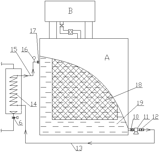
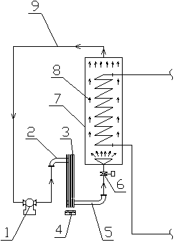
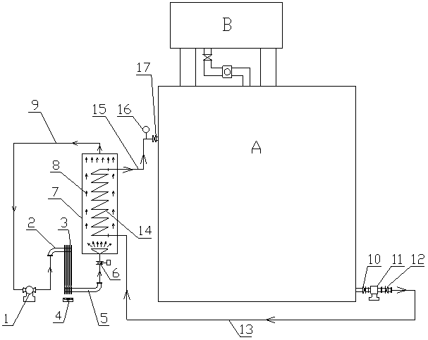
[0022] Such as Figure 1~3 shown, a SF 6 The cooling device of the main transformer as a cold medium consists of a transformer oil flow circulation system and SF 6 Composed of refrigerant circulation system, the transformer oil flow circulation system includes main transformer body A, oil pump 11 and SF 6 The transformer oil flow path 14 of the evaporator 7, the main transformer body A is filled with transformer oil 19 for cooling the coil and the iron core 18, and the upper part of the main transformer body A is provided with a cold oil inlet for inputting cold transformer oil And the cold oil inlet valve 17, the lower part of the main transformer body A is provided with a hot oil outlet for outputting thermal transformer oil and a hot oil outlet valve 10, and the oil pump 11 transports the thermal transformer oil 19 from the hot oil outlet to SF 6 The transformer oil flow path 14 inlet of the evaporator 7, the heat transformer oil is SF 6 SF surrounded by the transformer ...


PUM


Abstract

The invention relates to a main-transformation heat-dissipating device with SF6 (sulfur hexafluoride) as a refrigerant medium and a heat-dissipating method. The main-transformation heat-dissipating device consists of a transformer oil flow circulating system and an SF6 refrigerant medium circulating system, wherein the transformer oil flow circulating system comprises a main-transformation body, an oil pump, and a transformer oil flow passage of an SF6 evaporator; the main-transformation body is filled with transformer oil for cooling a coil and an iron core; a cold oil inlet is formed in the upper part of the main-transformation body; a hot oil outlet is formed in the lower part of the main-transformation body; the oil pump conveys hot transformer oil from the hot oil outlet to an inlet of the transformer oil flow passage of the SF6 evaporator; the hot transformer oil is cooled by an SF6 refrigerant inside the SF6 refrigerant circulating system and around the transformer oil flow passage, and flows from an outlet of the transformer oil flow passage of the SF6 evaporator to the cold oil inlet. The main-transformation heat-dissipating device has huge advantages of safety, reliability, high cooling efficiency, small equipment volume, low oil consumption, less maintenance, economical overall operation and the like, and is a revolutionary innovation of a main-transformation cooling way.

Description

technical field [0001] The present invention relates to a kind of SF 6 A heat dissipation device and method for a main transformer with a cold medium. Background technique [0002] During the operation of the main transformer, due to the action of electricity and magnetism, its coil and iron core will generate heat. If the heat cannot be taken away in time, it will cause serious accidents such as burning or even explosion of the main transformer. The transformer oil flows to cool the coil and iron core, and the heat taken away by the transformer oil flow needs to be exchanged through the cooling device, and the cooled cold oil flow enters the main transformer body for cooling. Traditional main transformer cooling methods mainly include forced air cooling, natural air cooling and water cooling. Although water cooling is economical and efficient, if cooling water leaks into the main transformer in the cooling system, even if it is a small leak, It will lead to serious conseq...

Claims


Application Information

Patent Timeline
Patent Type & Authority Applications(China)
IPC IPC(8): H01F27/18H01F27/12F25B1/00
Inventor 林晓铭郑东升宋仕江林莉郑孝章叶雷林舒妍林碧莺康建生黄建贵
Owner STATE GRID CORP OF CHINA
Why Eureka
Try Eureka