Axial turbo machine

a technology of axial turbo machines and axial tubes, which is applied in the direction of machines/engines, stators, liquid fuel engines, etc., can solve the problems of increasing pressure loss (energy loss), and achieve the effect of reducing the fluid pressure loss

Inactive Publication Date: 2017-03-16
IHI CORP
View PDF1 Cites 2 Cited by
  • Summary
  • Abstract
  • Description
  • Claims
  • Application Information

AI Technical Summary

Benefits of technology

[0014]According to the present disclosure, the axial turbo machine that reduces the pressur

Problems solved by technology

Such a growth of the secondary flow vortex i

Method used


Image

  • Axial turbo machine
  • Axial turbo machine
  • Axial turbo machine

Examples


Embodiment Construction

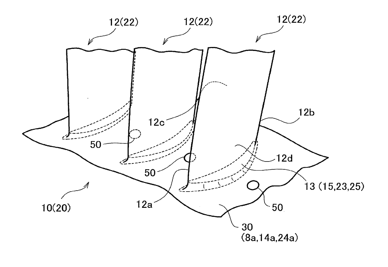
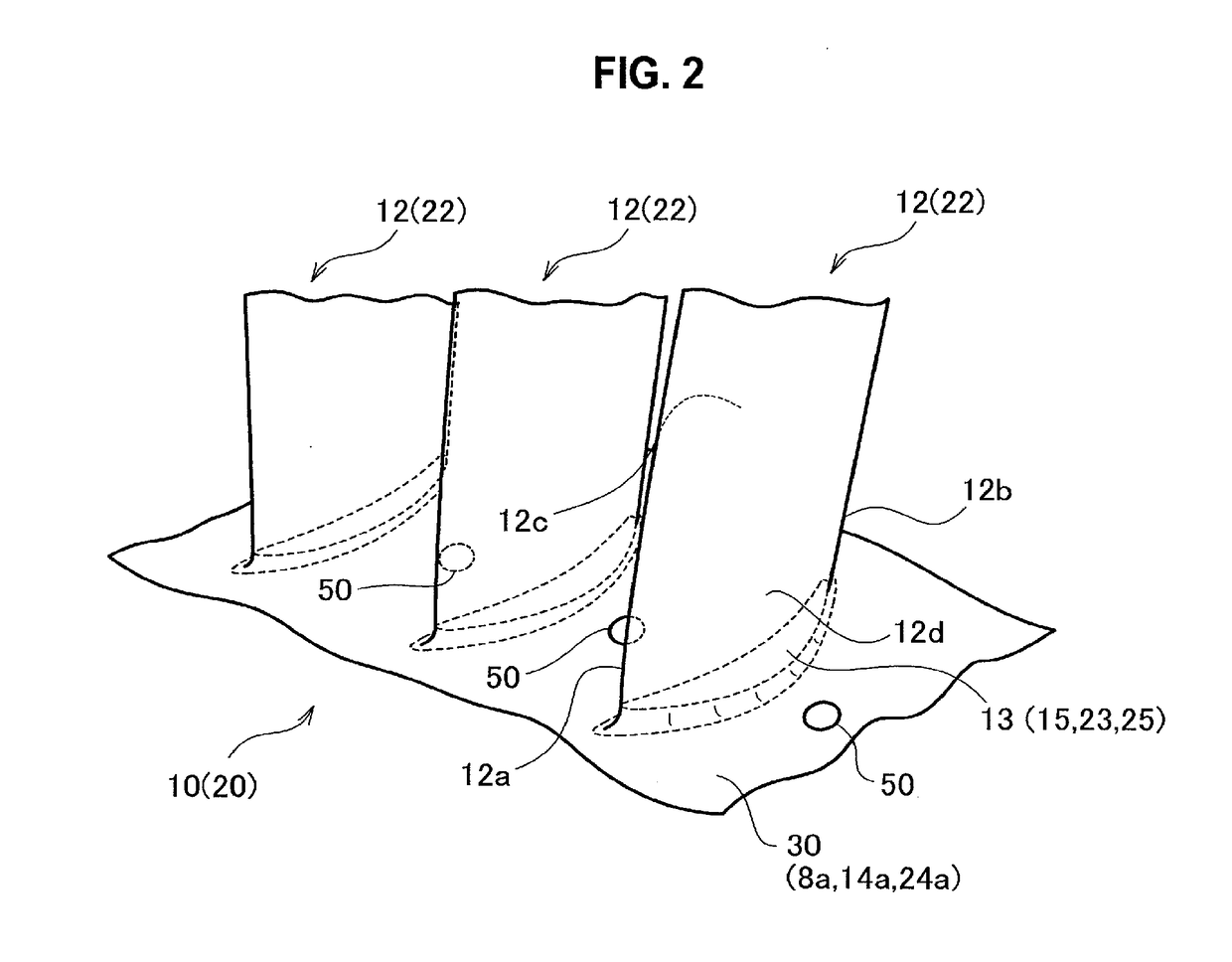
[0024]Hereinafter, an axial turbo machine (axial turbomachine) (or an end wall structure of the axial turbo machine) according to an embodiment of the present disclosure will be described on the basis of the attached drawings. Note that the same numerals are attached to parts that are common among the respective drawings, and repeated description thereof is omitted. The axial turbo machine according to the present embodiment is an axial gas turbine engine. Hereinafter, this gas turbine engine will be simply referred to as an engine for the convenience of description. Note that the axial turbo machine according to the present disclosure includes an aircraft turbofan engine, a turbojet engine, a turbo-prop engine, a turbo-shaft engine, a turbo-ram jet engine, a gas turbine for power generation, a marine gas turbine, and the like. However, the present disclosure is not limited to applications-use forms of them that have been exemplified.

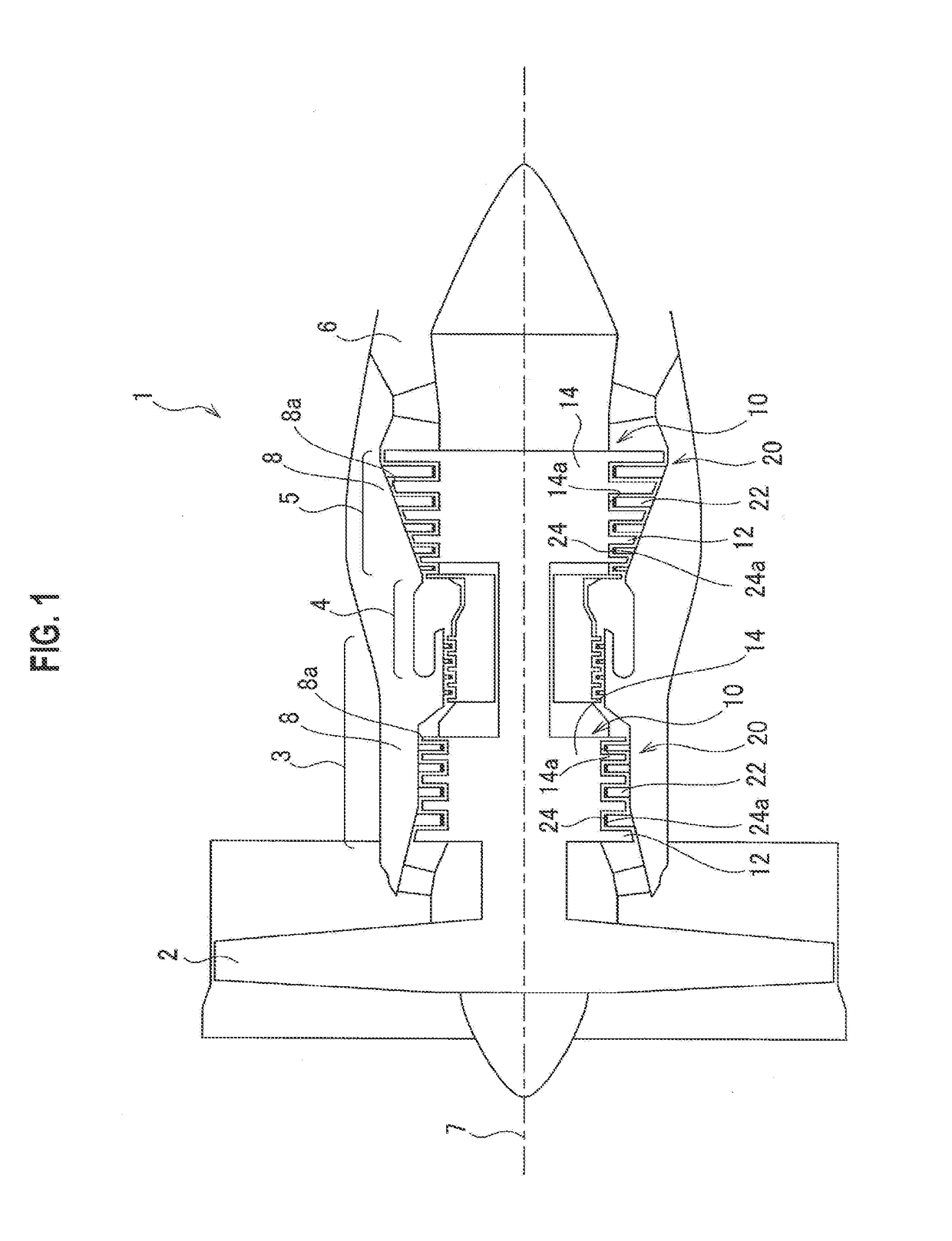
[0025]As shown in FIG. 1, an engine 1 is provided...


PUM


Abstract

An axial turbo machine includes: a plurality of blades that constitutes a moving blade row or a stationary blade row; an end wall 1 to which the plurality of blades is fixed and which forms a channel of a fluid together with the blades; and at least one concave portion that is locally formed in a region located between the adjacent blades or on the upstream side of a front edge of the blade on a surface of the end wall and that controls a secondary flow of the fluid.

Description

CROSS REFERENCE TO RELATED APPLICATIONS[0001]This application is a continuation application of International Application No. PCT / JP2015 / 070348, filed on Jul. 16, 2015, which claims priority to Japanese Patent Application No. 2014-164755, filed on Aug. 13, 2014, the entire contents of which are incorporated by reference herein.BACKGROUND[0002]1. Technical Field[0003]The present disclosure relates to an axial turbo machine that reduces a pressure loss of a fluid.[0004]2. Description of the Related Art[0005]The axial turbo machine such as a gas turbine engine has respective blade rows of moving blades and stationary blades which are alternately arranged along an axial direction. An end wall that forms a channel in the axial turbo machine together with the blade rows is provided inside or outside each of the blade rows in a radial direction. When the fluid flows into this channel, a secondary flow having a velocity component (a flow direction) different from that of the mainstream is ge...

Claims


Application Information

Patent Timeline
IPC IPC(8): F01D5/02F01D9/04F01D5/12F04D29/32F04D29/54
CPCF01D5/02F04D29/324F04D29/542F01D5/12F05D2250/712F05D2220/32F05D2250/141F05D2250/12F01D9/041F04D29/321F04D29/681F01D5/143F01D5/145Y02T50/60
Inventor TAKAHASHI, AKIRAHAMABE, MASAAKI
Owner IHI CORP
Why Eureka
Try Eureka