Lens Unit and Rear-Side Focus Adjustment System of Infrared Camera

a technology of infrared camera and rear-side focus, which is applied in the direction of camera focusing arrangement, printers, instruments, etc., can solve the problems of affecting the image quality of the container, the position of the detection surface can easily deviate, and the inability to check the internal state of the container from the outside, so as to maintain the image quality of the infrared camera, high performance level, and high accuracy

Active Publication Date: 2017-05-25
TAMRON
View PDF2 Cites 2 Cited by
  • Summary
  • Abstract
  • Description
  • Claims
  • Application Information

AI Technical Summary

Benefits of technology

[0011]A lens unit and a rear-side focus adjustment system for infrared cameras, according to the present invention are capable of performing rear-side focus adjustments even when the position of the detection surface of an infrared sensor is unknown. Therefore, according to the lens unit and the rear-side focus adjustment system of infrared camera according to the present invention, it is possible to continuously keep imaging the performance of the infrared camera at a high performance level, even when the mounting of the lens unit on the camera body is not performed with a high accuracy.

Problems solved by technology

Bolometer-type infrared sensor is not easily influenced by thermal convection and the like that causes degradation of detection accuracy and is vacuum-locked in a container composed of metal or the like.
Therefore, a position of the detection surface can easily deviate during the manufacturing process, and it is not possible to check an internal state of the container from the outside.
Even a slight deviation of the detection surface of the infrared sensor results in error where the position of the rear-side focus of the lens unit does not match the detection surface.
That makes it becomes difficult to automatically control the position of the focus adjustment lens, and it becomes impossible to obtain a clear image.

Method used


Image

  • Lens Unit and Rear-Side Focus Adjustment System of Infrared Camera
  • Lens Unit and Rear-Side Focus Adjustment System of Infrared Camera

Examples


Embodiment Construction

]

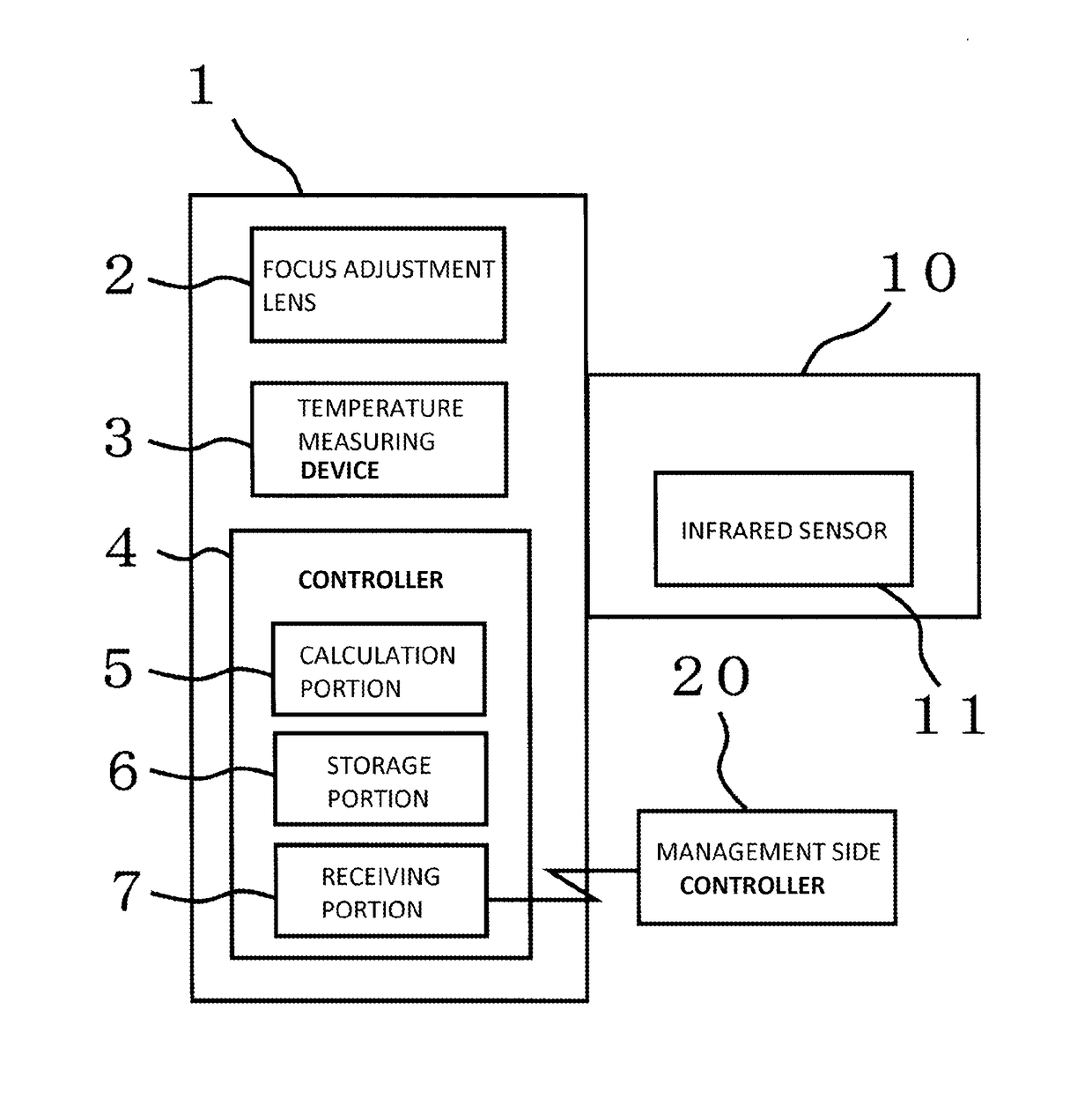
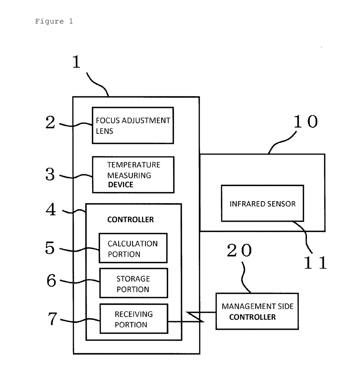
[0013]A preferable embodiment of a lens unit and a rear-side focus adjustment system of an infrared camera according to the present invention is described below with reference to FIG. 1.

[0014]FIG. 1 is a block diagram showing the construction of the rear-side focus adjustment system for infrared cameras. The rear-side focus adjustment system of infrared camera according to the present invention is a rear-side focus adjustment system of infrared camera equipped with a Camera body 10 that detects infrared light with Infrared sensor 11 and performs a process for converting the infrared light to an image signal; Lens unit 1 that is detachably mounted on Camera body 10. Note that Camera body 10 is equipped with Infrared sensor 11 having a detection surface for detecting infrared light. Further, Lens unit 1 is equipped with Focus adjustment lens 2, and Control means 4 for controlling the position of Focus adjustment lens 2. Control means 4 calculates a rear-side focus adjustment amount f...


PUM


Abstract

A lens unit and a rear-side focus adjustment system for infrared cameras capable of performing rear-side focus adjustments even when the position of the detection surface of an infrared sensor is unknown in an infrared camera. The lens unit is detachably mounted on a camera body that detects infrared light with an infrared sensor and converts the infrared light to an image signal, the lens unit including a focus adjustment lens and controller. The controller calculates a rear-side focus adjustment amount for causing a rear-side focus position to correspond to the detection surface based on an error between an actually measured focused position of the focus adjustment lens relative to an object at a particular object distance and a theoretically focused position of the focus adjustment lens calculated based on the object distance and controls the position of the focus adjustment lens based on the rear-side focus adjustment amount.

Description

TECHNICAL FIELD[0001]The present invention relates to a lens unit and a rear-side focus adjustment system of an infrared camera, and in particular to a lens unit and a rear-side focus adjustment system of an infrared camera, which are capable of performing a rear-side focus adjustment even when the position of the detection surface of an infrared sensor is unknown in an infrared camera.BACKGROUND ART[0002]Recently, an infrared camera that detects infrared rays radiated from an object to perform object recognition has been widely used for the purpose of security in darkness. In this connection, when using the infrared camera for the purpose of security, it is necessary to obtain a clear image, and for that purpose, it is necessary to accurately form infrared light transmitted through a lens group in a lens unit into an image on a detection surface of an infrared sensor. To achieve cost reduction, however, so-called “bolometer type” is often used. Bolometer-type infrared sensor is not...

Claims


Application Information

Patent Timeline
Patent Type & Authority Applications(United States)
IPC IPC(8): H04N5/232G02B7/02G02B7/09H04N5/33G02B13/14
CPCH04N5/33G02B13/14H04N5/23212G02B7/028G02B7/09G02B7/36G03B3/10H04N23/671
Inventor UEYAMA, YUICHI
Owner TAMRON
Why Eureka
Try Eureka