OLED display and display module thereof

Active Publication Date: 2017-09-14
TCL CHINA STAR OPTOELECTRONICS TECH CO LTD
View PDF2 Cites 0 Cited by
  • Summary
  • Abstract
  • Description
  • Claims
  • Application Information

AI Technical Summary

Benefits of technology

[0015]In comparison with the prior art, the OLED display and the display module thereof provided by the present invention, the reflectivities among the layers of the luminance function are satisfied with a following relationship, which is the reflectivity of the material of the luminance function layer near to the cathode plate is greatly higher than the reflectivity of another material of the luminance function layer distant from the cathode plate. It solves the technical problem of decreasing the contrast and sharpness of the OLED display caused by the cathode plate with the high reflectivity. In addition, to satisfy that the reflectivity of

Problems solved by technology

However, in a production line, the ITO is always formed on a bottom, since an ITO deposition damages the organic material.
A general solution i

Method used


Image

  • OLED display and display module thereof
  • OLED display and display module thereof
  • OLED display and display module thereof

Examples


Embodiment Construction

[0020]Embodiments of the present invention are described in detail with the technical matters, structural features, achieved objects, and effects with reference to the accompanying drawings as follows. It is clear that the described embodiments are part of embodiments of the present invention, but not all embodiments. Based on the embodiments of the present invention, all other embodiments to those of ordinary skill in the premise of no creative efforts obtained, should be considered within the scope of protection of the present invention.

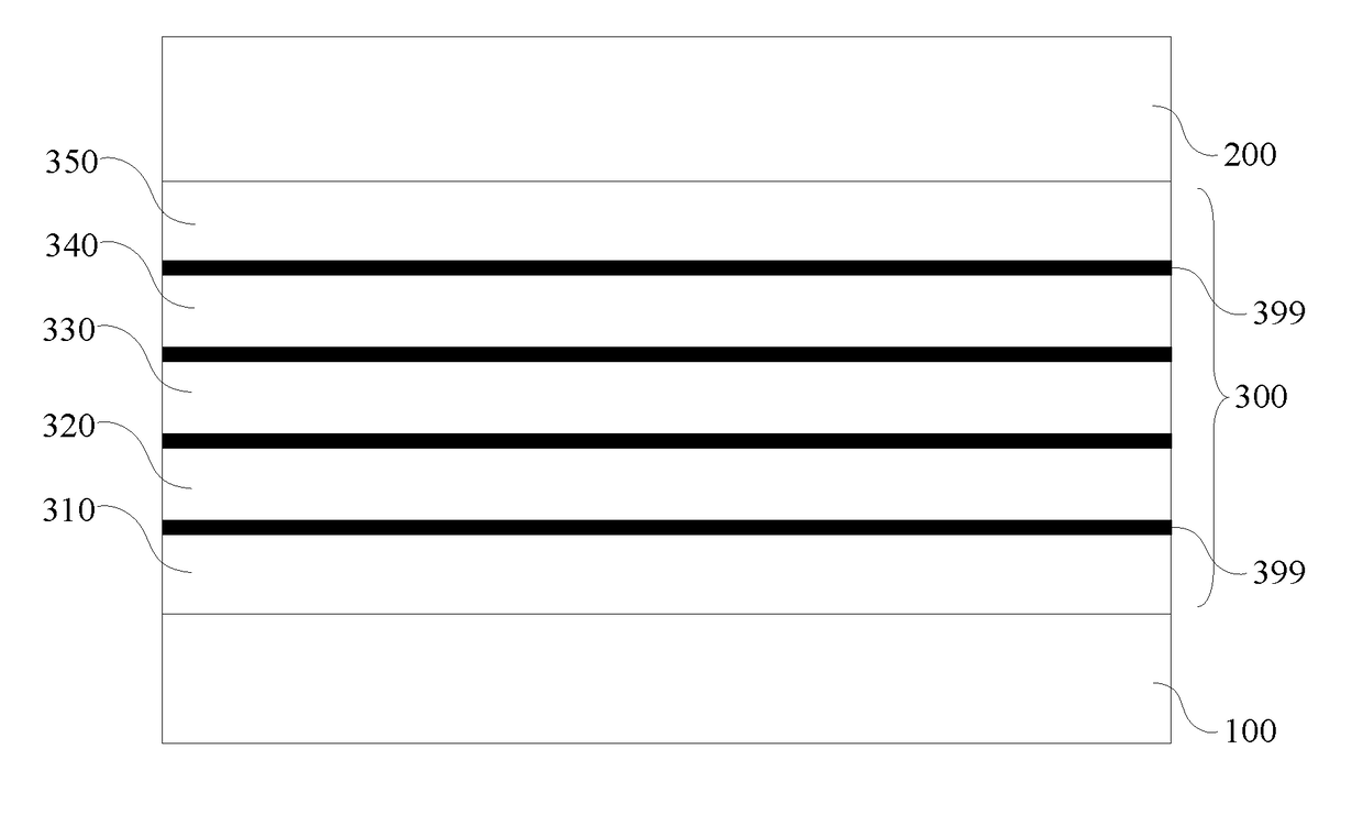
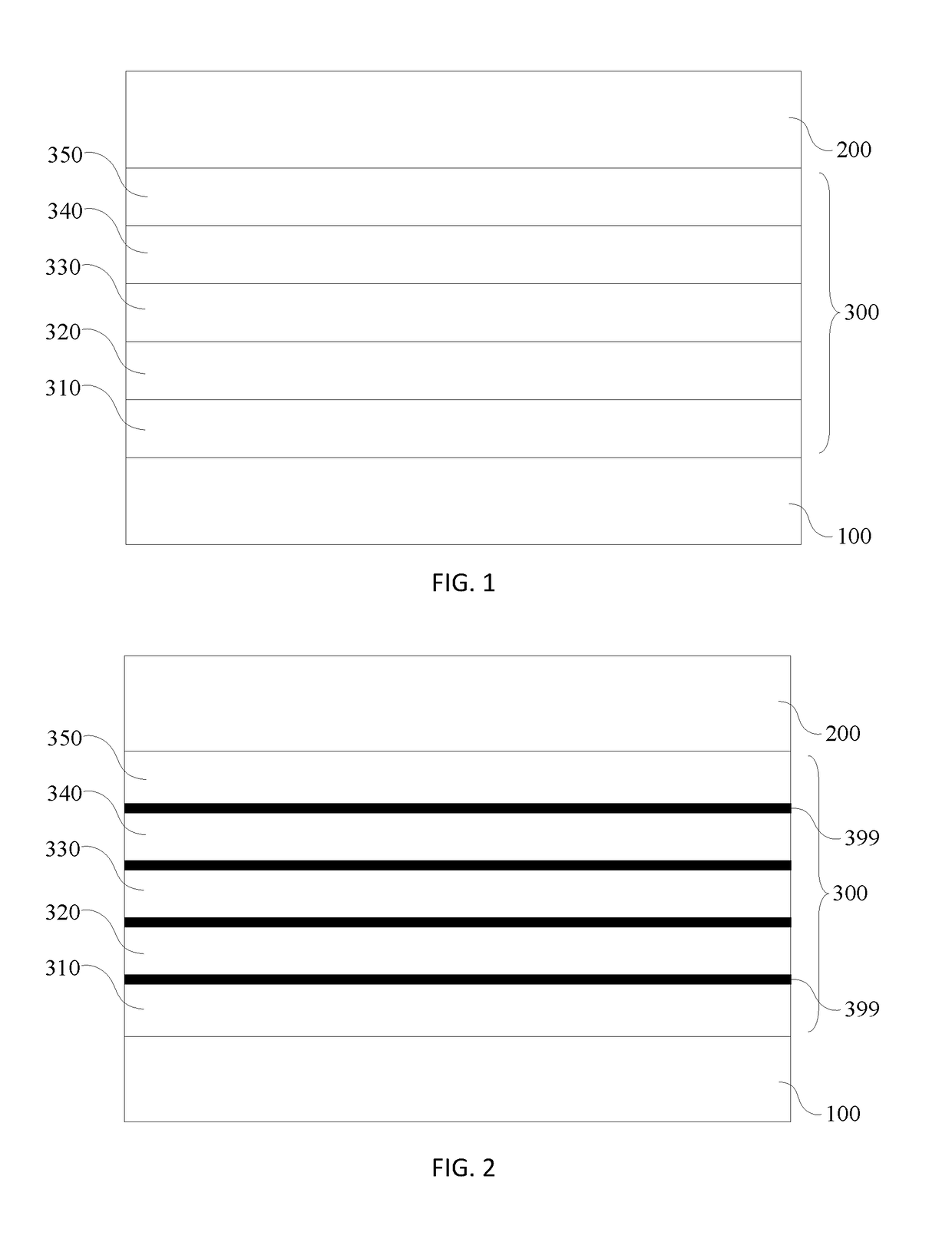
[0021]Please refer to FIG. 1. FIG. 1 is structural schematic drawing of an OLED display module of a preferred embodiment of the present invention. The OLED display module comprises: a cathode plate 100, an anode plate 200 and a luminance function layer 300 sandwiched in between the cathode plate 100 and the anode plate 200. Multiple reflectivities among multiple layers of the luminance function layer 300 are satisfied with a following relationship,...


PUM


Abstract

The present disclosure provides an OLED display and display module thereof. The OLED display module includes: a cathode plate, an anode plate and a luminance function layer sandwiched in between the cathode plate and the anode plate, and characterized in that multiple reflectivities among multiple layers of the luminance function layer are satisfied with a following relationship, which is a reflectivity of the material of the luminance function layer near to the cathode plate is greatly higher than a reflectivity of another material of the luminance function layer distant from the cathode plate. The display module solves the technical problem of decreasing the contrast and sharpness of the OLED display caused by the cathode plate with the high reflectivity.

Description

FIELD OF THE INVENTION[0001]The present invention relates to a technology field of an OLED display, and more particularly to an OLED display and a display module thereof.BACKGROUND OF THE INVENTION[0002]The organic electroluminesence diode (OLED) element is composed of a cathode, an anode and a luminance layer. The cathode is made of Al etc. metal material and the anode is made of ITO etc. material. Electrons and holes are respectively injected to the cathode and the anode to form excitons in the organic luminance layer to excite the luminance layer to luminesce. The present product in the laboratory mainly employs a transparent ITO anode. The element structure presents a condition of a top emission. However, in a production line, the ITO is always formed on a bottom, since an ITO deposition damages the organic material. Thus, a structure of a bottom emission is employed and lights are emitted from the cathode.[0003]Currently, most of OLED employ an anode-luminance structure and the...

Claims


Application Information

Patent Timeline
IPC IPC(8): H01L51/52H01L51/50
CPCH01L51/5293H01L51/0077H01L51/5092H01L51/5072H01L51/5016H01L51/5221H01L2251/558H01L2251/301H01L51/0078H01L51/005H01L51/0084H01L51/0061H01L51/0072H01L51/0067H01L51/0081H01L51/5206H10K59/00H10K50/85H10K50/856H10K50/868H10K50/11H10K50/16H10K50/81H10K50/82H10K50/171H10K85/30H10K85/60H10K85/311H10K85/324H10K85/341H10K85/636H10K85/654H10K85/6572H10K2101/10H10K2102/00H10K2102/351
Inventor CHEN, LIXUAN
Owner TCL CHINA STAR OPTOELECTRONICS TECH CO LTD
Why Eureka
Try Eureka