Lighting device and display device

a technology of light source and light source, which is applied in the direction of optical light source, instruments, optics, etc., can solve the problems of reducing the uneven amount of light in the plate surface of reducing the uneven amount of light inside the light source plate, so as to achieve the effect of reducing uneven brightness

Active Publication Date: 2018-02-15
SHARP KK
View PDF7 Cites 13 Cited by
  • Summary
  • Abstract
  • Description
  • Claims
  • Application Information

AI Technical Summary

Benefits of technology

[0024]In the present invention, the uneven brightness is reduced.

Problems solved by technology

In general, the amount of light inside the light guide plate is likely to insufficient at the position near the border between the fan-shaped areas adjacent to each other, but the above-described configuration reduces the unevenness in amount of light in the plate surface of the light guide plate.

Method used


Image

  • Lighting device and display device
  • Lighting device and display device
  • Lighting device and display device

Examples


first embodiment

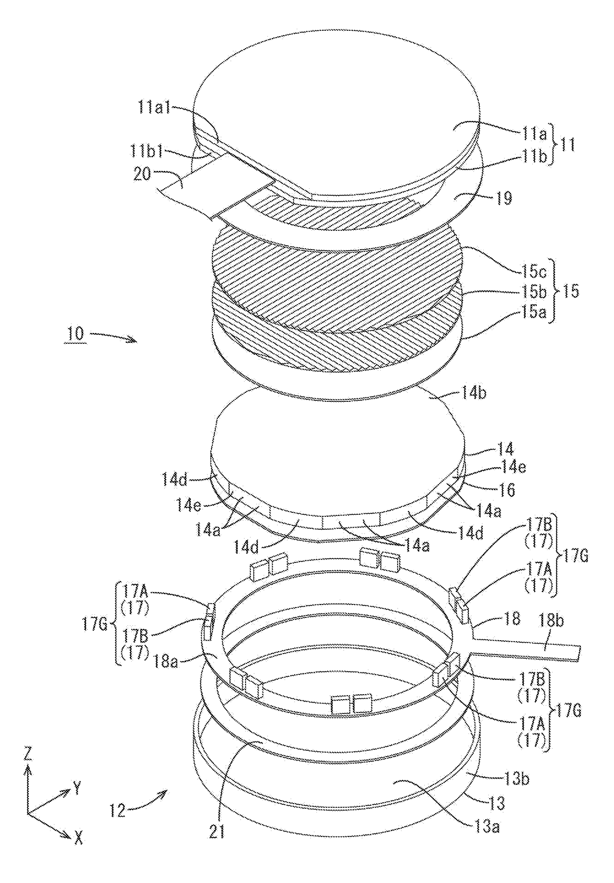
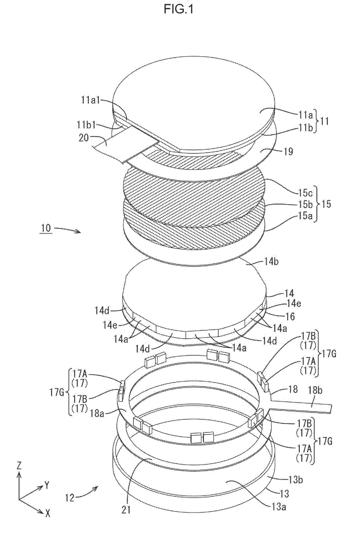
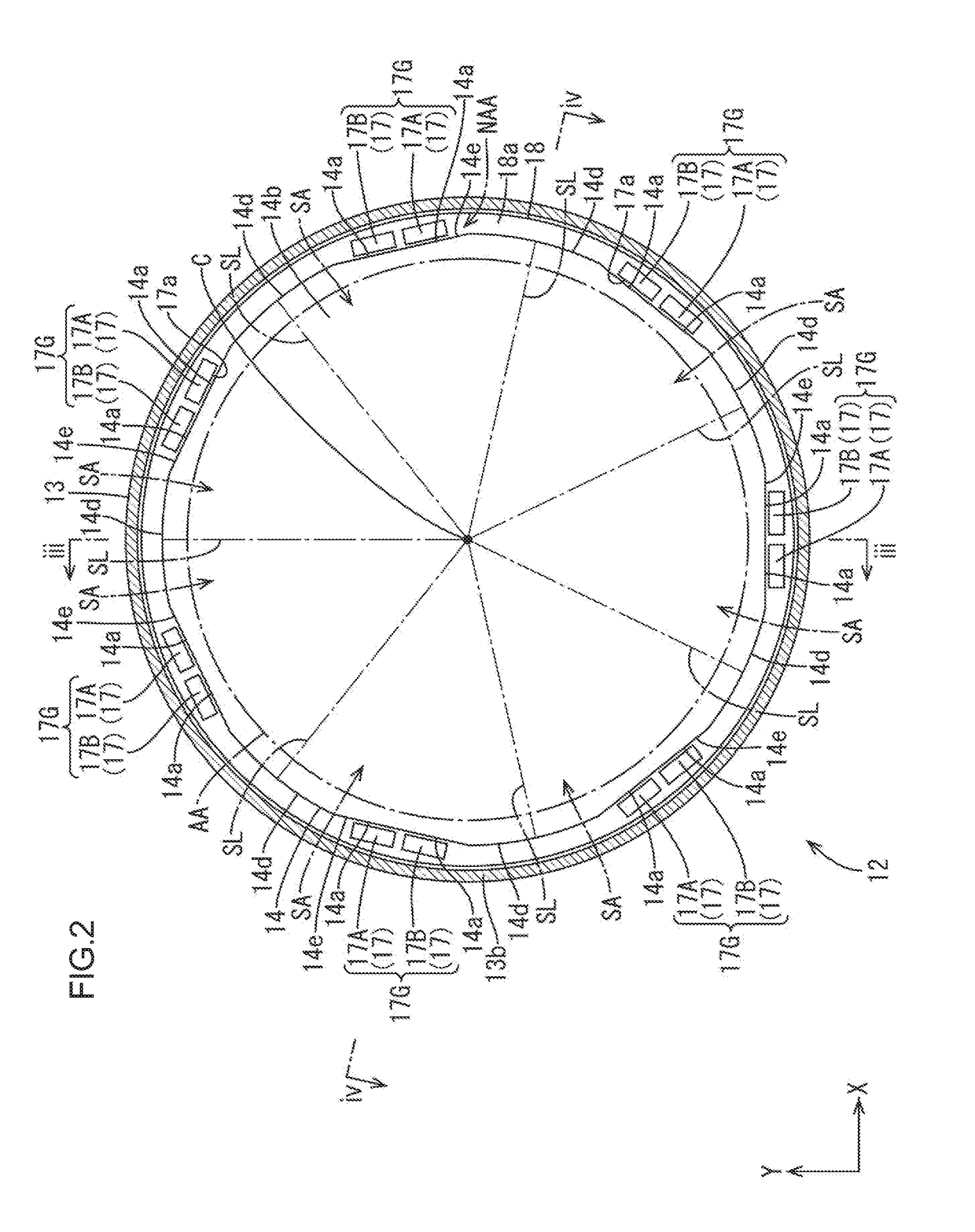
[0042]A first embodiment of the invention is described with reference to FIG. 1 to FIG. 7. In this embodiment, as a display panel, a liquid crystal display device (a display device) 10 including a liquid crystal panel 11 is described as an example. The X axis, the Y axis, and the Z axis are indicated in some of the drawings, and each of the axes indicates the same direction in the drawings. The up and down direction is based on that of FIG. 3 and FIG. 4, and the upper side and the lower side are a front side and a rear side, respectively.

[0043]The liquid crystal display device 10 has a substantially circular overall shape, and at least includes, as illustrated in FIG. 1, a liquid crystal panel (a display panel) 11, which is configured to display an image, and a backlight device (a lighting device) 12, which is located on a rear side of the liquid crystal panel 11 and configured to apply light to the liquid crystal panel 11 for displaying an image. Although not illustrated, the liqui...

second embodiment

[0081]A second embodiment of the invention is described with reference to FIG. 8 or FIG. 9. In the second embodiment, the arrangement of LEDs 117 are in a different arrangement and the shape of cutouts 114e in a light guide plate 114 are different. The configurations, operations, and effects similar to those in the first embodiment are not described.

[0082]As illustrated in FIG. 8, two LEDs 117 constituting an LED group 117G according to this embodiment are arranged such that light-emitting surfaces 117a thereof are tilted with respect to each other. Specifically, the light-emitting surfaces 117a of the two LEDs 117 constituting the LED group 117G form an angle larger than 180 degrees, i.e., a major angle. As illustrated in FIG. 9, a first LED 117A of the two LEDs 117 has a light-emitting surface 117a facing a segment line SL between the fan-shaped areas SA adjacent to each other in the clockwise direction (side away from a second LED 117B adjacent to the first LED 117A in the circum...

third embodiment

[0086]A third embodiment of the invention is described with reference to FIG. 10 to FIG. 12. In the third embodiment, the number of LED groups 217G and the number of LEDs 217 constituting each LED group 217G differ from those in the above-described first embodiment. The configurations, operations, and effects similar to those in the first embodiment are not described.

[0087]As illustrated in FIG. 10, the number of LED groups 217G in this embodiment is five (an odd number larger than three), and each LED group 217G includes three LEDs 217. Specifically, the five LED groups 217G are arranged with an equal distance therebetween in the circumferential direction of the light guide plate 214, and the central angle between the LED groups 217G adjacent to each other in the circumferential direction is about 72 degrees. Thus, line segments each connecting the middle between two of the three LEDs 217 located at ends (the central position of the LED 217 at the center) in each of the LED groups ...


PUM


Abstract

A backlight device 12 includes a light guide plate 14, LEDs 17, and wiring portions 18c. The light guide plate 14 has a substantially circular outer shape and has fan-shaped areas SA defined by segment lines SL extending through a center C thereof. All the segment lines SL meet at the center C. The LEDs 17 include sets of LEDs 17 provided for the fan-shaped areas SA. The LEDs 17 are arranged such that middle positions between LEDs 17 each located at an end in the circumferential direction in the respective sets of the LEDs 17 provided for the fan-shaped areas SA adjacent to each other in the circumferential direction coincides with the segment lines SL. The wiring portions 18c are equal or larger in number than the LEDs 17 included in each of the sets of LEDs 17 provided for the fan-shaped areas SA and are configured to supply electric power to the respective LEDs 17 provided for the fan-shaped areas SA.

Description

TECHNICAL FIELD[0001]The present invention relates to a lighting device and a display device.BACKGROUND ART[0002]A liquid crystal display device has been conventionally used as a display device in a small and thin device such as a notebook computer, a mobile phone, and a mobile television. In addition, a liquid crystal display device is increasingly used as a display device of an automotive instrument for displaying vehicle information or traffic information. Such a liquid crystal display device includes a lighting device configured to illuminate the liquid crystal panel. The lighting device includes a light source and a light guide plate configured to convert a light flux emitted by the light source into a planar light flux suitable for illumination of the liquid crystal panel. One known example of the lighting device of this kind is described in Patent Document 1 listed below. Patent Document 1 describes a lighting device including a light source and a light guide member. The ligh...

Claims


Application Information

Patent Timeline
Patent Type & Authority Applications(United States)
IPC IPC(8): F21V8/00
CPCG02B6/0083G02B6/009G02B6/0068G02B6/0073G02B6/0021G02B6/0045G02B6/002
Inventor MURATA, MITSUHIROYUKI, RYUZOWATANABE, HISASHIKADOWAKI, SHINYAISHIDA, TAKESHIMASUDA, TAKESHI
Owner SHARP KK
Why Eureka
Try Eureka