Method for measuring displacements of object

a technology of displacement measurement and object, applied in the field of measuring equipment, can solve the problems of limited transducer sensitivity, low measurement accuracy, limited measurement range, etc., and achieve the effect of increasing the efficiency of production managemen

Active Publication Date: 2018-04-19
MEDVEDEVA MARINA VLADIMIROVNA +1
View PDF4 Cites 0 Cited by
  • Summary
  • Abstract
  • Description
  • Claims
  • Application Information

AI Technical Summary

Benefits of technology

[0029]When using this method it is possible to obtain precise information about the time and plac...

Problems solved by technology

Thus, the accuracy of object position detection depends on the value of the measuring range of transducers, which in turn depends on and is limited to the area of the transducer sensitivity.
The disadvantages of this method are the low accuracy of measuring and limited measurement range due to transducers sensitivity area.
Thus, it considerably complicates the measurement system.
The disadvantage of these methods is the inability to measure the object position outside the area of transducer sensitivity that does not allow to measure movement of the object to considerable distances, and thereby limits the use in production.
The disadvantage of this method is the low accuracy, as far as the value of object movem...

Method used


Image

  • Method for measuring displacements of object

Examples


Embodiment Construction

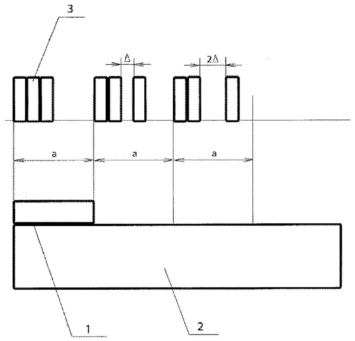
[0031]For instance, as a transducer there is the magnetostrictive linear displacement transducer 1 set on a moving object. It has a displacement measurement range a. Along the object path the magnets and / or electromagnets 3 are placed. Let's consider the case when at each path section a the same number of magnets and / or electromagnets is used, but the distance between the two magnets and / or electromagnets is being changed (see FIG. 1). So at the first path section equal to the measuring range a of the magnetostrictive displacement transducer, the magnets and / or electromagnets are placed close to each other to form a first unique set. At the second similar path section with the length a the second set of magnets and / or electromagnets is located, in which, for example, the rightmost magnet and / or electromagnet is moved aside at the distance Δ. At the third similar path section with the length a the third set of magnets and / or electromagnets is located, in which, for example, the right...


PUM


Abstract

The invention relates to measurement technology and is used to determine the absolute displacements of objects in metallurgy, automotive industry, warehouse and production logistics, and in the automation of production. The technical result is achieved when the following steps are performed: the displacement transducer is mounted on the object; signal sources are mounted along the trajectory of the object displacement; on each section of the trajectory, an arrangement of the signal sources is provided which is determined by changing the number of signal sources and/or the distance between any two signal sources; a signal is sent to the moving object with transducer; an output signal is received from the transducer regarding the location of the signal sources located within the measurement range; the object location is determined; furthermore, the displacement is measured at a distance exceeding the length of the active zone of the transducer.

Description

CROSS REFERENCE TO RELATED APPLICATIONS[0001]The present patent application is National stage application from PCT application PCT / RU2016 / 000227 filed on Apr. 21, 2016 which claims priority to Russian patent applications RU2015127430 filed Jul. 8, 2015 and RU2015152019 filed Dec. 4, 2015, all of which incorporated herein by reference entirely.FIELD OF INVENTION[0002]The invention relates to the measuring equipment and can be used to determine the absolute displacement of objects in such areas as, for example, metallurgy, automotive industry, cranes, warehouse and production logistics, the production automation as a whole.BACKGROUND[0003]When expending operational tasks in production, increasing of production process efficiency plays an important role. It can be achieved in particular due to fast and accurate object positioning at different periods of time within the production facilities. Effective monitoring of object movements allows creating an exact map of the production process...

Claims


Application Information

Patent Timeline
IPC IPC(8): G01D5/48
CPCG01D5/485G01C22/00G01D5/247G01P13/00G01D5/48
Inventor MEDVEDEVA, MARINA VLADIMIROVNAUTKIN, KONSTANTIN BORISOVICH
Owner MEDVEDEVA MARINA VLADIMIROVNA
Why Eureka
Try Eureka