High-pressure pump control device for internal combustion engine

a technology of high-pressure pump and control device, which is applied in the direction of electric control, fuel injecting pump, machines/engines, etc., can solve the problems of reducing the pressure of fuel supplied to the high-pressure pump, and the life of the high-pressure pump is likely to be shorter, so as to prevent or restrict the cavitation erosion occurring inside the high-pressure pump and prolong the life of the high-pressure pump

Active Publication Date: 2018-05-10
DENSO CORP
View PDF9 Cites 2 Cited by
  • Summary
  • Abstract
  • Description
  • Claims
  • Application Information

AI Technical Summary

Benefits of technology

[0010]According to the configuration as above, when it is predicted that a discharge quantity of the high-pressure pump exceeds a discharge quantity of the low-pressure pump, a discharge quantity of the high-pressure pump can be restricted not to exceed a predetermined value by executing the discharge quantity ...

Problems solved by technology

Hence, a discharge quantity of the high-pressure pump may temporarily exceed a discharge quantity of the low-pressure pump, for example, in a process of fuel pressure rising when transition from a low-load low-fuel pressure state to a high-load high-fuel pressure state is taking place while the internal combustion engine is rotating at a high speed due to an increase in fuel consumption for a high load or an increase in fuel ...

Method used


Image

  • High-pressure pump control device for internal combustion engine
  • High-pressure pump control device for internal combustion engine
  • High-pressure pump control device for internal combustion engine

Examples


first embodiment

[0023]A first embodiment of the present disclosure will now be described according to FIG. 1 to FIG. 6.

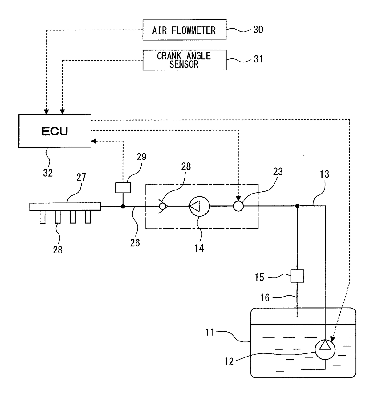
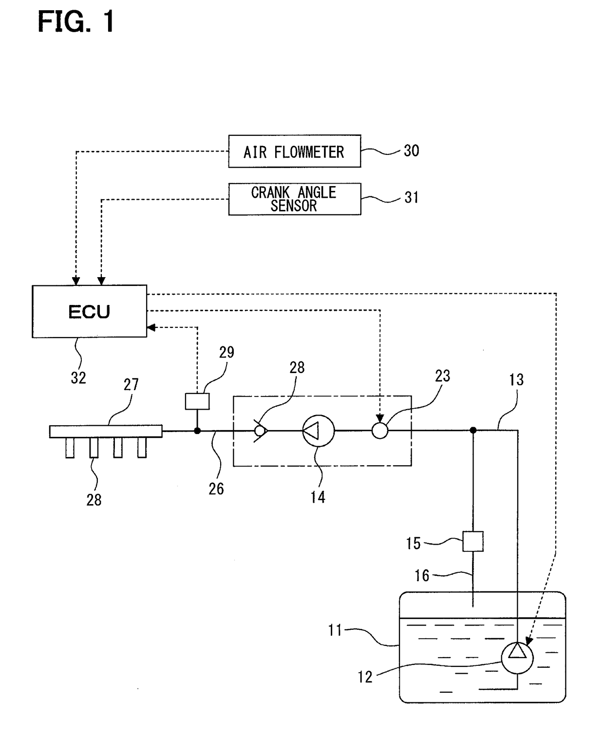
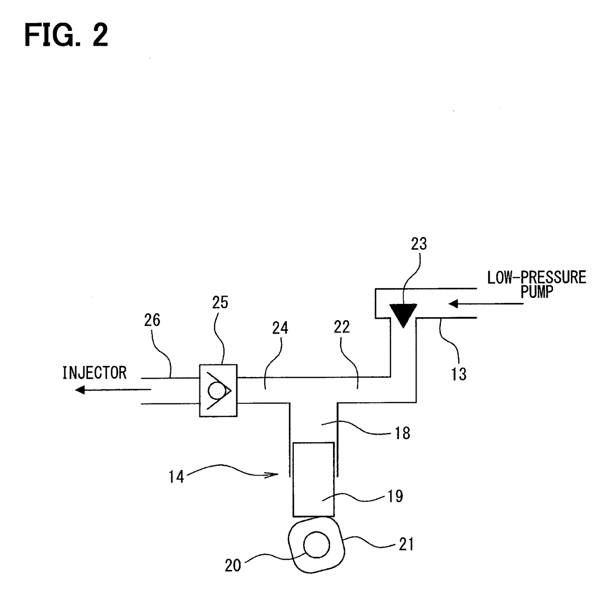
[0024]Firstly, a schematic configuration of a fuel supply system of an in-cylinder injection engine (internal combustion engine) will be described according to FIG. 1 and FIG. 2.

[0025]As is shown in FIG. 1, a low-pressure pump 12 pumping up fuel is provided in a fuel tank 11 where fuel is stored. The low-pressure pump 12 is driven by an electric motor (not shown) using a battery (not shown) as a power supply. Fuel discharged from the low-pressure pump 12 is supplied to a high-pressure pump 14 through a fuel pipe 13. A pressure regulator 15 is connected to the fuel pipe 13. A discharge pressure (that is, a fuel supply pressure to the high-pressure pump 14) of the low-pressure pump 12 is regulated at a predetermined pressure by the pressure regulator 15. Excessive fuel exceeding the predetermined pressure is returned to the fuel tank 11 through a fuel returning pipe 16.

[0026]As is sh...

second embodiment

[0055]A second embodiment of the present disclosure will now be described using FIG. 7 and FIG. 8. The following will chiefly describe a difference from the first embodiment above and portions substantially same as the portions of the first embodiment above will not be described repetitively or described only briefly.

[0056]In the second embodiment, the ECU 32 executes an F / B control quantity calculation routine of FIG. 7 to execute a discharge quantity restriction control by restricting an F / B control quantity by restricting a fuel pressure deviation used to calculate the F / B control quantity.

[0057]In the F / B control quantity calculation routine of FIG. 7, a deviation of an actual fuel pressure from a target fuel pressure is calculated as a fuel pressure deviation [MPa] in 201 in accordance with Equation (2) above.

[0058]Subsequently, advancement is made to 202, in which engine fuel consumption quantity per hour [L / hr] is calculated according to an engine speed [rpm] and an engine lo...

third embodiment

[0066]A third embodiment of the present disclosure will now be described using FIG. 9 and FIG. 10. The following will chiefly describe a difference from the first and second embodiments above and portions substantially same as the portions of the first and second embodiments above will not be described repetitively or described only briefly.

[0067]In the third embodiment, the ECU 32 executes an F / B control quantity calculation routine of FIG. 9 to perform a discharge quantity restriction control by restricting an F / B control quantity by restricting a target fuel pressure.

[0068]In the F / B control quantity calculation routine of FIG. 9, engine fuel consumption quantity per hour [L / hr] is calculated according to an engine speed [rpm] and an engine load (for example, an intake air quantity or an intake air pressure), and a target fuel pressure guard correction value corresponding to the engine speed and the engine fuel consumption quantity is calculated with reference to a map of a targe...


PUM


Abstract

A high-pressure pump control device is applied to an internal combustion engine including a high-pressure pump supplied with fuel discharged from a low-pressure pump and an injector supplied with fuel discharged from the high-pressure pump. The high-pressure pump control device includes a prediction unit predicting whether a discharge quantity of the high-pressure pump exceeds a discharge quantity of the low-pressure pump and a restricting unit executing a discharge quantity restriction control to restrict a discharge quantity of the high-pressure pump not to exceed a predetermined value when the prediction unit predicts that a discharge quantity of the high-pressure pump exceeds a discharge quantity of the low-pressure pump.

Description

CROSS REFERENCE TO RELATED APPLICATION[0001]This application is based on Japanese Patent Application No. 2015-106221 filed on May 26, 2015, the disclosure of which is incorporated herein by reference.TECHNICAL FIELD[0002]The present disclosure relates to a high-pressure pump control device applied to an internal combustion engine which supplies an injector with fuel discharged from a high-pressure pump.BACKGROUND ART[0003]In an in-cylinder injection internal combustion engine configured to inject fuel directly into a cylinder, a time from injection to combustion is short in comparison with an intake port injection internal combustion engine configured to inject fuel to an intake port. Hence, a time secured to atomize injected fuel is so short that it is necessary to turn injected fuel to fine particles by increasing an injection pressure to a high pressure. Accordingly, in the in-cylinder injection internal combustion engine, fuel pumped up from a fuel tank using an electric low-pre...

Claims


Application Information

Patent Timeline
IPC IPC(8): F02D1/06F02M59/36F02M51/04
CPCF02D1/06F02M59/36F02M51/04F02D2001/009F02D41/3845F02D2041/1412F02D2041/142F02D2200/0602F02D2250/31F02D41/3854
Inventor HIRATA, YASUO
Owner DENSO CORP
Why Eureka
Try Eureka