Control Valve with External Relief Bias Member

a technology of bias member and control valve, which is applied in the direction of machine/engine, process and machine control, instruments, etc., can solve the problems of difficult configuration of actuator and valve to provide adequate valve movement and pressure relief in a compact configuration, and achieve the effect of increasing the volume of the material

Active Publication Date: 2018-06-07
ROSTRA VERNATHERM
View PDF47 Cites 2 Cited by
  • Summary
  • Abstract
  • Description
  • Claims
  • Application Information

AI Technical Summary

Benefits of technology

[0011]A pre-determined increase in the temperature of the material results in a pressure acting on the piston that is sufficient to overcome the bias force of the return bias member. This pressure moves the valve member away from the cap from a cold position to a hot position. An increase in temperature beyond this hot position results in a continued increase in the volume of the material. This change in volume causes greater pressure on the piston that compresses the relief bias member, allowing the abutment to move towards the closed end of the cap from the operational position to the relief position.

Problems solved by technology

While wax-filled actuators have gained wide acceptance in temperature control systems, it can be difficult to configure an actuator and valve to provide adequate valve movement and pressure relief in a compact configuration.
This is especially difficult when a relief bias member is incorporated into the control valve that accommodates over-extension of the actuator at temperatures above the normal operating range for the system.

Method used


Image

  • Control Valve with External Relief Bias Member
  • Control Valve with External Relief Bias Member
  • Control Valve with External Relief Bias Member

Examples


Embodiment Construction

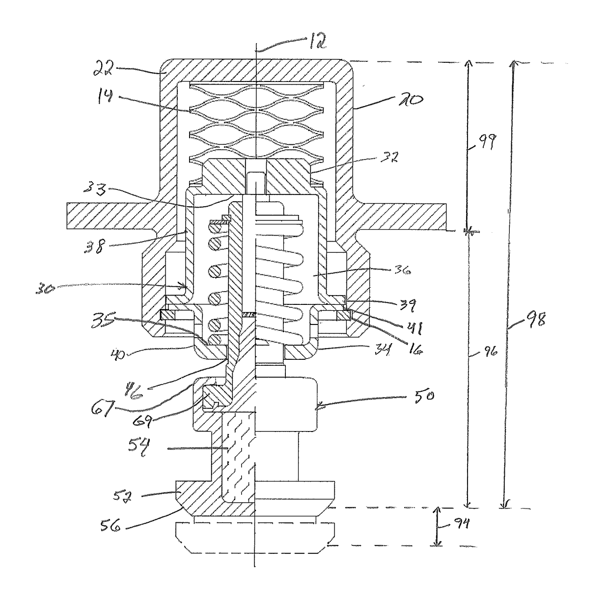
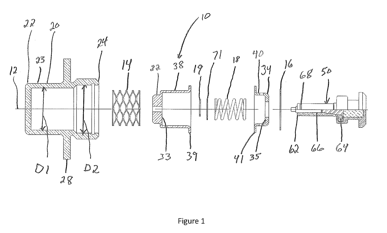
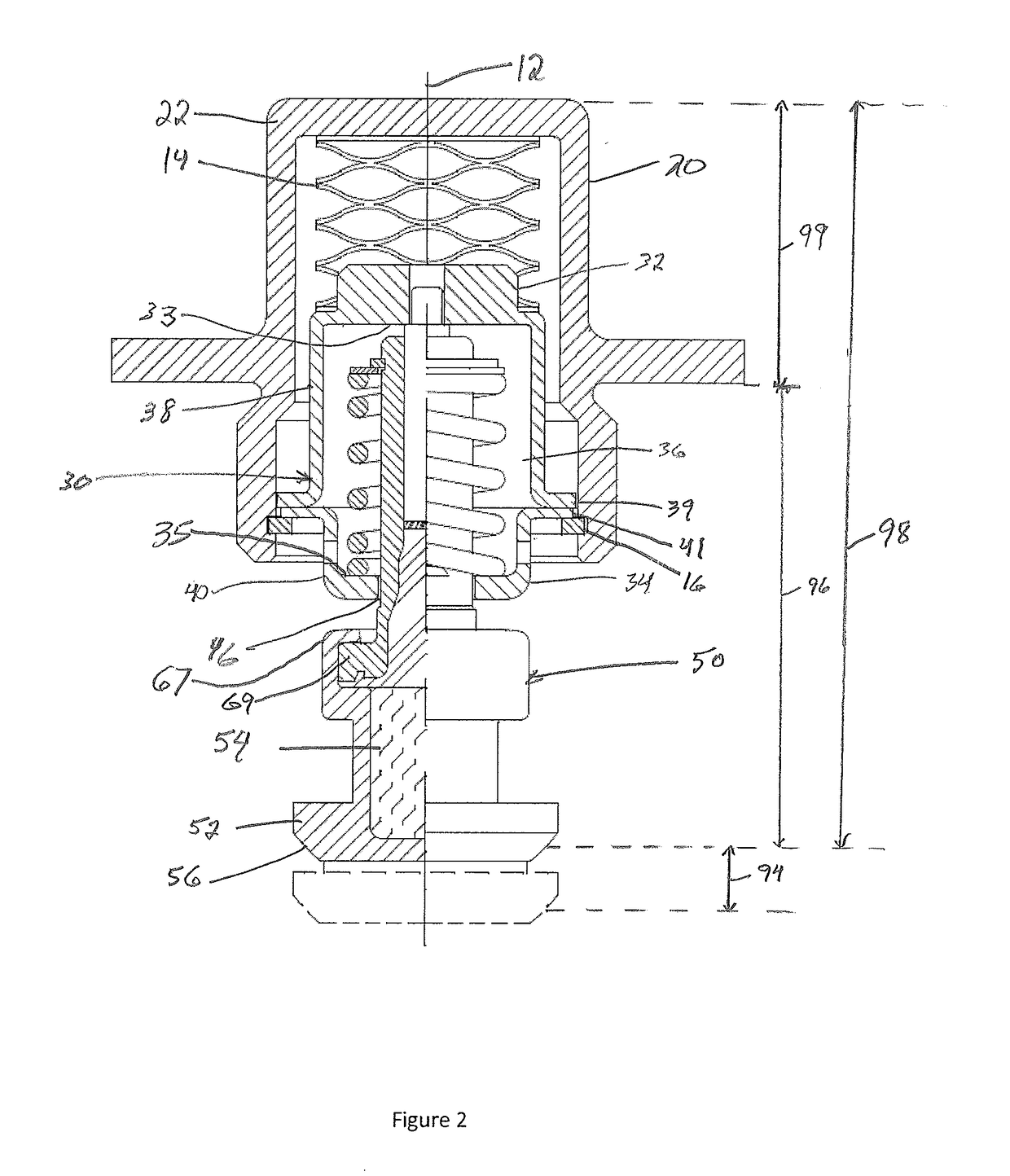
[0018]With reference to FIGS. 1-4B, wherein like numerals represent similar parts throughout the several figures, a first embodiment of a control valve with a relief bias member outside of a fluid housing is generally designated by the reference numeral 10 (hereafter “control valve 10”). The control valve 10 is configured to provide reliable and efficient control of fluids through a system as the temperature of the fluid in the system changes. The present disclosure primarily describes a control valve 10 for use in fluid systems requiring valve movement that is large relative to the distance between an outer wall and the valve seat of a chamber.

[0019]Referring to one embodiment of the control valve 10, depicted in FIGS. 1 and 2, a cap 20 forms a hollow cylindrical chamber, though other shapes may be used. The cap 20 has a closed end 22 transverse to a longitudinal axis 12 and a side wall 23 that extends axially away from the closed end 22 to an open end 24. The side wall 23 has a fi...


PUM


Abstract

A thermally actuated flow control valve mounted to a housing to control fluid flow based on temperature is provided. The control valve has a relief bias member in a cap projecting outside of the housing. Within the housing, the control valve has an actuator extending into a return bias container and a valve member. The actuator includes a thermally responsive material that expands and contracts in response to fluid flow over a predetermined range of temperatures. The actuator extends to close the valve member against a valve seat within the housing when the thermally responsive material expands. A return member moves the valve member away from the valve seat when the thermally responsive material contracts. The return bias container allows the relief bias member to accommodate pressures and temperatures beyond the predetermined range.

Description

BACKGROUND OF THE DISCLOSURE[0001]The present disclosure relates to thermally actuated flow-control valves. More particularly, the present disclosure relates to valves including wax-filled actuators employed to control the flow of coolant to heat producing components in engine systems.[0002]The wax actuator conventionally comprises a rigid housing surrounding a reservoir filled with wax formulated to transition from solid to liquid in response to a predictable increase in temperature. The housing is made of strong, thermally conductive material, such as brass, although other materials may be suitable. A piston is arranged to reciprocate in a guide that defines a bore in communication with the reservoir. A flexible diaphragm, plug, or other seal arrangement may be disposed between the wax and the piston to contain the wax in the reservoir. The wax expands in volume as the wax becomes a liquid, generating a force that is directed into the bore of the guide, and pushes the piston away ...

Claims


Application Information

Patent Timeline
Patent Type & Authority Applications(United States)
IPC IPC(8): F16K17/00F16K31/00F16K1/12G05D23/12
CPCF16K17/003G05D23/121F16K1/12F16K31/002F01P7/16F01P11/18F16K11/0716F16K31/0613G05D23/021G05D23/022G05D23/1333
Inventor LAMB, KEVIN W.LIONELLO, KENNETH
Owner ROSTRA VERNATHERM
Why Eureka
Try Eureka