Method and system for controlling a downhole flow control device

Active Publication Date: 2007-08-16
BAKER HUGHES INC
View PDF13 Cites 0 Cited by
  • Summary
  • Abstract
  • Description
  • Claims
  • Application Information

AI Technical Summary

Benefits of technology

[0009]In one aspect, the present invention provides a system for controlling a downhole flow control device that includes a flow control device at a downhole location in a well wherein the flow control device has a movable element for controlling a downhole formation flow. The movable element has a hydraulic seal associated therewith. The seal is constructed such that a maximum pressure of an applied pressure pulse is sufficient to overcome a static friction force associated with the seal, and wherein a minimum pressure of an applied pressure pulse is insufficient to overcome a dynamic friction force associated with the seal.

Problems solved by technology

The seal is constructed such that a maximum pressure of an applied pressure pulse is sufficient to overcome a static friction force associated with the seal, and wherein a minimum pressure of an applied pressure pulse is insufficient to overcome a dynamic friction force associated with the seal.

Method used


Image

  • Method and system for controlling a downhole flow control device
  • Method and system for controlling a downhole flow control device
  • Method and system for controlling a downhole flow control device

Examples


Embodiment Construction

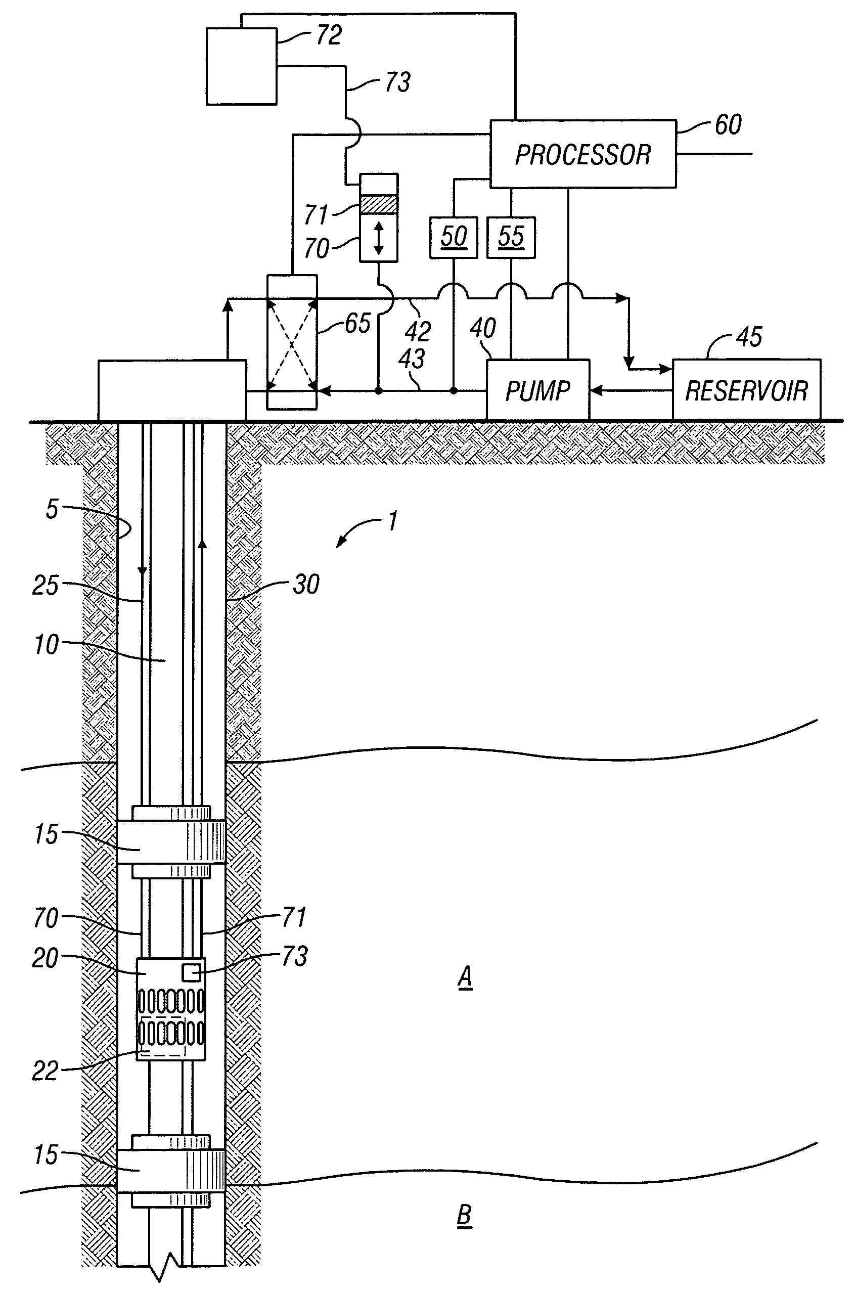
[0016]As is known, a given well may be divided into a plurality of separate zones which are required to isolate specific areas of a well for purposes including, but not limited to, producing selected fluids, preventing blowouts, and preventing water intake.

[0017]With reference to FIG. 1, well 1 includes two exemplary zones, namely zone A and zone B, where the zones are separated by an impermeable barrier. Each of zones A and B have been completed in a known manner. FIG. 1 shows the completion of zone A using packers 15 and sliding sleeve valve 20 supported on tubing string 10 in wellbore 5. The packers 15 seal off the annulus between the wellbore and a flow control device, such as sliding sleeve valve 20, thereby constraining formation fluid to flow only through open sliding sleeve valve 20. Alternatively, the flow control device may be any flow control device having at least one moveable element for controlling flow, including, but not limited to, a downhole choke and a downhole sa...


PUM


Abstract

A system for controlling flow in a wellbore uses a downhole flow control device positioned at a downhole location in the wellbore. The flow control device has a movable element for controlling a downhole fluid flow. In response to an applied pressure pulse, the movable element moves in finite increments from one position to another. In one embodiment, a hydraulic source generates a transmitted pressure pulse to the flow control device wherein the maximum pressure of a received pressure pulse downhole is sufficient to overcome a static friction force associated with the movable element, and wherein a minimum pressure of the received pressure pulse downhole is insufficient to overcome a dynamic friction force associated with the movable element.

Description

CROSS-REFERENCE TO RELATED APPLICATION[0001]NoneBACKGROUND OF THE INVENTION[0002]1. Field of the Invention[0003]This invention relates generally to the control of oil and gas production wells. More particularly, it relates to control of movable elements in well production flow control devices.[0004]2. Description of the Related Art[0005]The control of oil and gas production wells constitutes an on-going concern of the petroleum industry due, in part, to the enormous monetary expense involved in addition to the risks associated with environmental and safety issues. Production well control has become particularly important and more complex in view of the industry wide recognition that wells having multiple branches (i.e., multilateral wells) will be increasingly important and commonplace. Such multilateral wells include discrete production zones which produce fluid in either common or discrete production tubing. In either case, there is a need for controlling zone production, isolatin...

Claims


Application Information

Patent Timeline
Patent Type & Authority Applications(United States)
IPC IPC(8): E21B43/12
CPCE21B23/04E21B34/16E21B34/10
Inventor VACHON, GUY P.
Owner BAKER HUGHES INC
Why Eureka
Try Eureka