Dental imaging device

a technology of dental imaging and x-ray, which is applied in the field of dental imaging devices, can solve the problems that the method described in the international application pct/ep2015/074896 may be long in its implementation and the comparison of various photos does not always yield satisfactory results, and achieves the effect of accelerating the acquisition process

Active Publication Date: 2018-10-25
DENTAL MONITORING
View PDF3 Cites 28 Cited by
  • Summary
  • Abstract
  • Description
  • Claims
  • Application Information

AI Technical Summary

Benefits of technology

[0016]As will become more clearly apparent later on in the description, a device according to the first main refinement of the invention thus allows multiple images of the teeth, observed from different angles, to be acquired simultaneously. The acquisition process is accelerated as a result.
[0017]In addition, determining the conditions for acquiring the direct image, or the reflected image, makes it possible to determine the conditions for acquiring the reflected image, or the direct

Problems solved by technology

The method described in international application PCT/EP2015/074896 may therefore be lengthy in

Method used


Image

  • Dental imaging device
  • Dental imaging device
  • Dental imaging device

Examples


Embodiment Construction
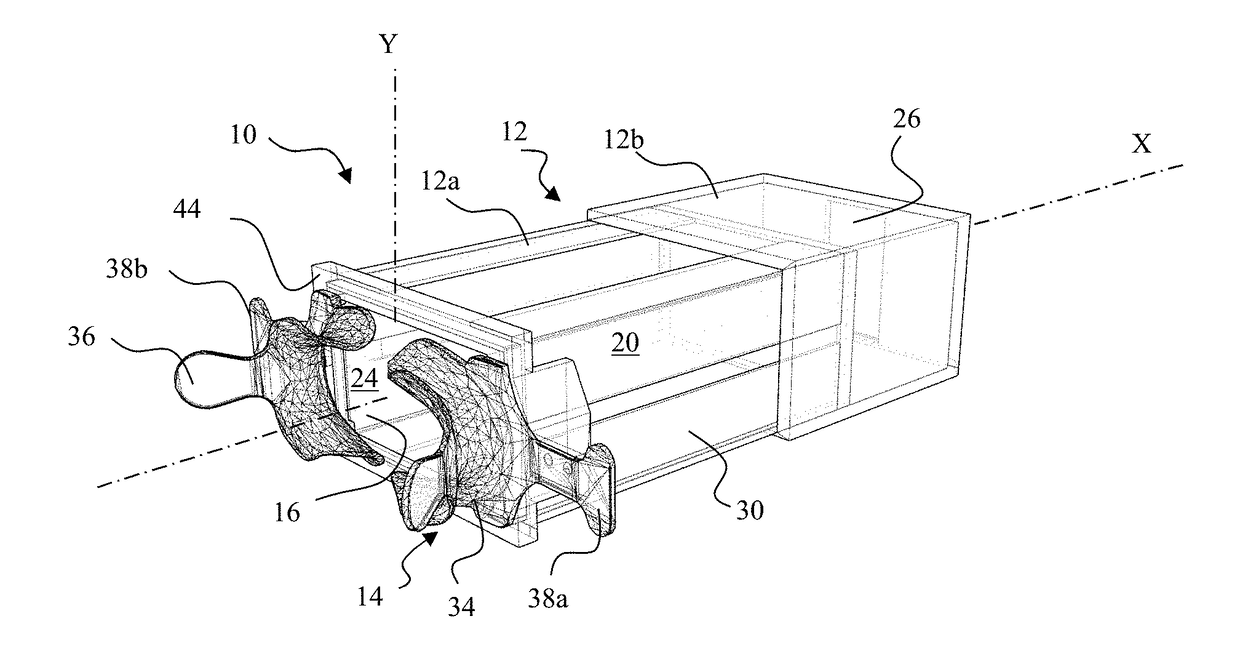
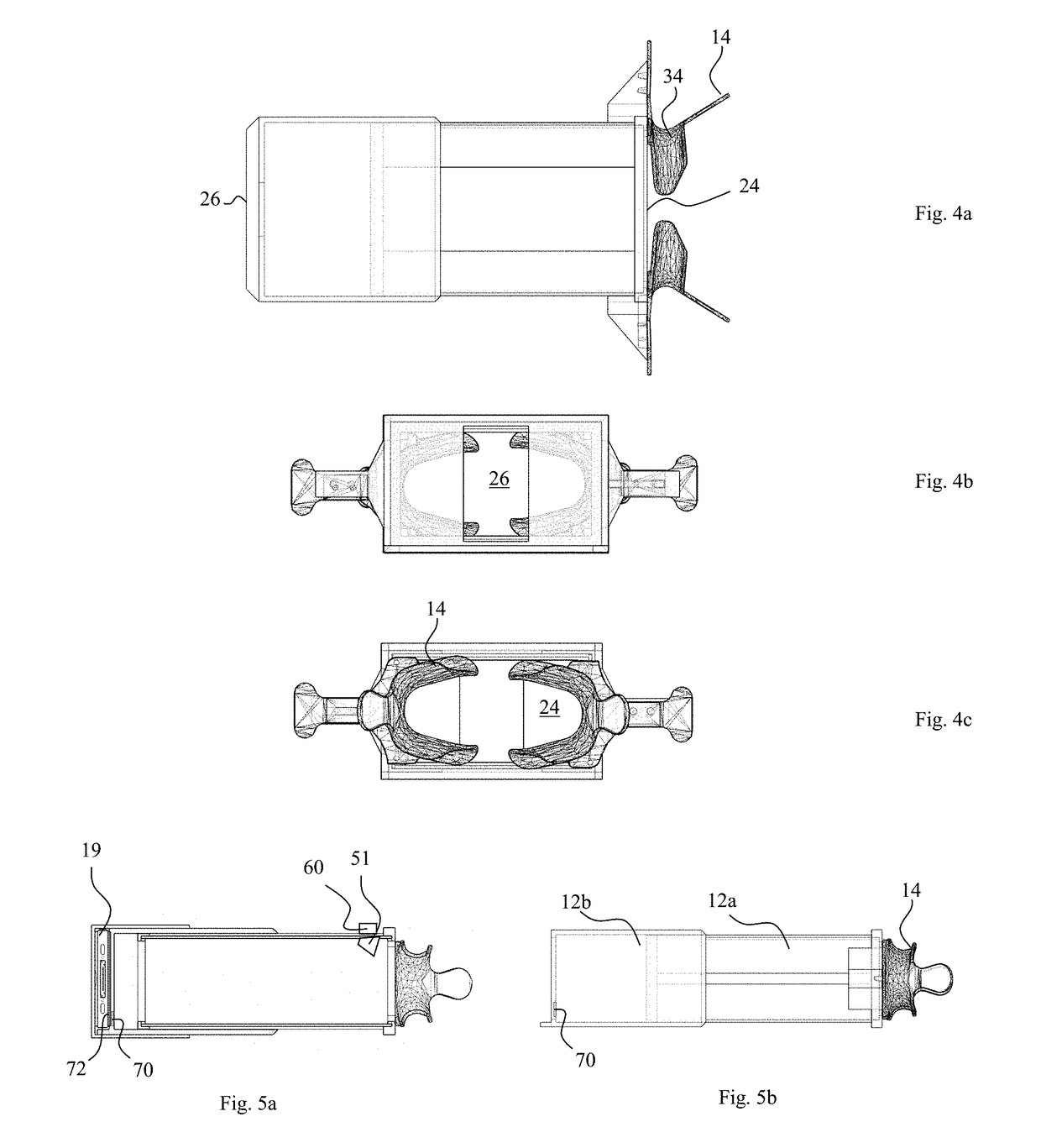
[0079]Device

[0080]The imaging device 10 shown in FIG. 1 includes a support 12, taking the form of an, optionally telescopic, box, a dental retractor 14, preferably at least one mirror 16, and fastening means 18 of an image acquisition apparatus 19, shown in FIG. 2.

[0081]In one embodiment, the support 12 includes a male portion 12a and a female portion 12b that are mounted so as to slide one inside the other, along a retractor axis X, between retracted (FIG. 5a) and deployed (FIG. 5b) positions.

[0082]In one embodiment, a scale is arranged on the male portion 12a of the support. Preferably, this scale provides indications facilitating the adjustment of the length, along the X axis, of the support 12, for example by bearing a mark for each type of image acquisition apparatus.

[0083]The support 12 defines a chamber 20, the length of which along the X axis depends on the relative position of the male and female portions of the support 12 when the box is telescopic, or is constant.

[0084]In...


PUM


Abstract

An imaging device including a support, a mouth retractor fastened to the support and defining a retractor opening and structure for fastening an image acquisition apparatus to the support in a position in which the acquisition apparatus is oriented so as to receive an image of the retractor opening.

Description

TECHNICAL FIELD[0001]The present invention relates to a dental imaging device, in particular for implementing a method such as described in international application PCT / EP2015 / 074896.PRIOR ART[0002]PCT / EP2015 / 074896 describes a method allowing, on the basis of[0003]a three-dimensional model of the teeth of a patient produced before treatment, referred to as the “initial reference model”, then[0004]a simple “updated” image of the teeth taken during treatment, for example a photograph taken by the patient,the positioning of the teeth at the moment of acquisition of the updated image to be accurately evaluated.[0005]This method consists in an iterative process in which, upon each iteration, models of teeth from the initial reference model are moved, then optimum conditions for observing the initial model thus modified (referred to as the “test reference model”) are determined, the optimum observation conditions being defined as the conditions allowing the test reference model to be ob...

Claims


Application Information

Patent Timeline
IPC IPC(8): A61C5/90G06T7/70H04N5/235A61B1/00A61B1/06A61B1/247A61C1/08
CPCA61C5/90G06T7/70H04N5/2351A61B1/00006A61B1/00057A61B1/0669A61B1/247A61C1/088A61B5/6844A61B1/24A61B5/0088A61B5/682A61B2560/0233A61B1/00016A61B1/00148H04N23/71
Inventor SALAH, PHILIPPEDEBRAUX, LAURENTPELLISSARD, THOMASGHYSELINCK, GUILLAUME
Owner DENTAL MONITORING
Why Eureka
Try Eureka