Shielded connector

a shielding and connector technology, applied in the direction of coupling devices, securing/insulating coupling contact members, two-part coupling devices, etc., can solve the problems of increased manufacturing cost, management cost and the like, and reduce the number of components , the effect of improving the shielding function

Active Publication Date: 2019-07-04
AUTONETWORKS TECH LTD +2
View PDF9 Cites 4 Cited by
  • Summary
  • Abstract
  • Description
  • Claims
  • Application Information

AI Technical Summary

Benefits of technology

[0013]In a state in which the lid portion is at the open position, the dielectric module can be inserted into the module housing portion through the insertion port. After the dielectric module is inserted into the module housing portion, the insertion port is closed by displacing the lid portion from the open position to the closed position. Since the outer conductor is a single component in which the module housing portion and the lid portion are integrated, the number of components can be reduced. Furthermore, a shielding function is improved in a region of the module housing portion where the outer plate portion overlaps. Still furthermore, the holding portion can prevent the dielectric from being separated due to interference of foreign matter, so that the dielectric module can be reliably housed in the module housing portion.

Problems solved by technology

In the shielded connector described above, since the outer conductor is constituted of two components, namely, the outer conductor body and the lid body, there is a problem that the manufacturing cost, the management cost and the like will be increased.

Method used


Image

  • Shielded connector
  • Shielded connector
  • Shielded connector

Examples


embodiment 1

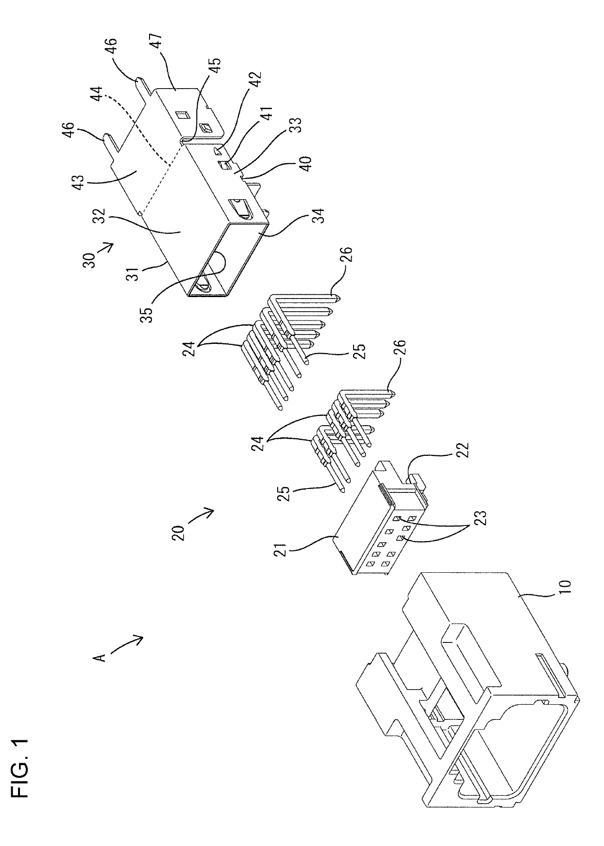
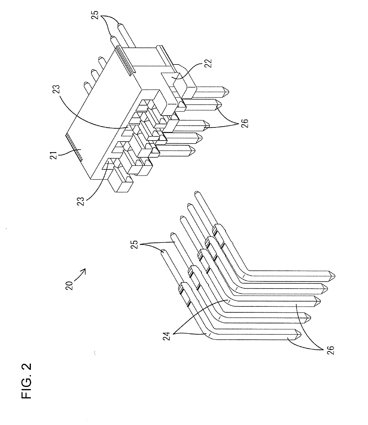
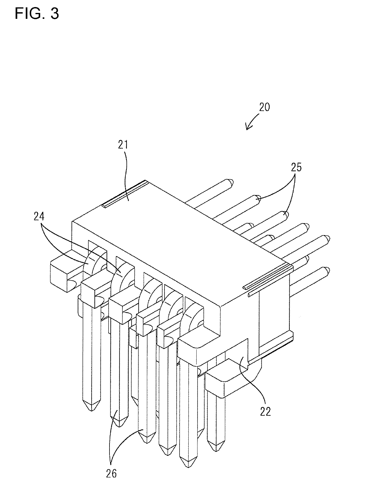
[0031]Hereinafter, Embodiment 1 in which the present invention is embodied will be described with reference to FIGS. 1 to 11. In the following description, as for the front-rear direction, the diagonally lower left side in FIG. 1, the diagonally upper right side in FIGS. 2 to 5, 7, 8, and 11, and the right side in FIGS. 6, 9, and 10 are defined as the front sides. For an up-down direction, the directions shown in FIGS. 1 to 3, 7, and 9 are defined as upward and downward as they are. In FIGS. 4, 5, 8, and 11, vertically inverted directions are shown.

[0032]A shielded connector A of Embodiment 1 is to be attached to an upper surface of a horizontally installed circuit board (not shown). The shielded connector A is constructed by assembling a housing 10 made of synthetic resin, a dielectric module 20, and an outer conductor 30. In the housing 10, the front end surface, the rear end surface, and the lower surface rear end portion are opened to the outside. Inside the housing 10, the diel...

embodiment 2

[0061]Next, Embodiment 2 in which the present invention is embodied will be described with reference to FIG. 12. In a shielded connector B of Embodiment 2, the projecting plate portion 38 is formed with a pair of right and left first earthing leg portions 51, and the lid portion 43 is formed with a pair of right and left second earthing leg portions 52. Since other configurations are the same as those of Embodiment 1, the same components are labeled by the same symbols as those of Embodiment 1, and explanation of the structure, operation, and effect thereof is omitted.

embodiment 3

[0062]Next, Embodiment 3 in which the present invention is embodied will be described with reference to FIG. 13. In a shielded connector C of Embodiment 3, the projecting plate portion 38 is formed with a pair of right and left first earthing leg portions 53, the lid portion 43 is formed with a pair of right and left second earthing leg portions 54, and furthermore, the right and left outer plate portions 47 are each formed with a third earthing leg portion 55 which is parallel to the first earthing leg portions 53 and the second earthing leg portions 54. Since other configurations are the same as those of Embodiment 1, the same components are labeled by the same symbols as those of Embodiment 1, and explanation of the structure, operation, and effect thereof is omitted.

Other Embodiments

[0063]The present invention is not limited to the above embodiments, which have been described using the foregoing description and the drawings, and, for example, embodiments as described below are a...


PUM


Abstract

A shielded connector (A) includes a dielectric module (20) having an L-shaped terminal fitting (24) attached to a dielectric (21) and an outer conductor (30) that houses the dielectric module (20). The outer conductor (30) is a single component having: a box-shaped module housing portion (31) with a front end surface opened as a first opening (35), a rear end region of a lower surface opened as a second opening (36), and a rear end surface opened as an insertion port (37) communicating with the second opening (36). A plate-shaped lid portion (43) is continuous with an opening edge of the insertion port (37). The plate-shaped lid portion (43) is displaced from an open position where the insertion port (37) is opened to allow the dielectric module (20) to be inserted into the module housing portion (31) to a closed position where the insertion port (37) is closed.

Description

BACKGROUNDField of the Invention[0001]The present invention relates to a shielded connector.Related Art[0002]Japanese Unexamined Patent Application Publication No. 2008-192474 discloses a shielded connector including a dielectric module having an L-shaped terminal fitting attached to a dielectric and an outer conductor which houses the dielectric module. The outer conductor is constructed by assembling an outer conductor body and a lid body. The outer conductor body has a box shape whose front end surface, rear end surface, and a lower surface rear end portion are opened, and the opening of the rear end surface and the opening of the lower surface rear end portion communicate with each other. The dielectric module is inserted into the outer conductor body through the opening of the rear end surface. After the dielectric module is inserted into the outer conductor body, the opening of a rear end surface of a dielectric body is closed with the lid body, whereby assembly of the outer c...

Claims


Application Information

Patent Timeline
Patent Type & Authority Applications(United States)
IPC IPC(8): H01R13/6581H01R13/6594H01R13/41
CPCH01R13/6581H01R13/6594H01R13/41H01R13/648H01R13/501H01R13/506H01R24/50H01R2103/00
Inventor MAESOBA, HIROYOSHIYOSHIDA, KAZUHIROICHIO, TOSHIFUMIYAMASHITA, MASANAO
Owner AUTONETWORKS TECH LTD
Why Eureka
Try Eureka