Display device and head-mounted display

a display device and display technology, applied in the direction of condensers, polarising elements, instruments, etc., can solve the problems of inferior light utilization efficiency, achieve high light utilization efficiency, improve display quality, and suppress display quality.

Active Publication Date: 2019-10-03
SHARP KK
View PDF8 Cites 2 Cited by
  • Summary
  • Abstract
  • Description
  • Claims
  • Application Information

AI Technical Summary

Benefits of technology

The present technology described in this patent aims to maintain display quality while keeping high efficiency of light utilization. It achieves this by using a low refraction index layer which facilitates the light emitted from the optical member to spread wider towards the end side of the display surface, making it less likely to be affected by foreign substances on the light path. As a result, display failures caused by foreign substances can be minimized, and the efficiency of the light utilization can be maintained, ultimately resulting in a better display quality.

Problems solved by technology

The liquid crystal display device disclosed in Patent Document 1 can improve visibility failure caused by a bright spot; however, utilization efficiency of light is inferior.

Method used


Image

  • Display device and head-mounted display
  • Display device and head-mounted display
  • Display device and head-mounted display

Examples


first embodiment

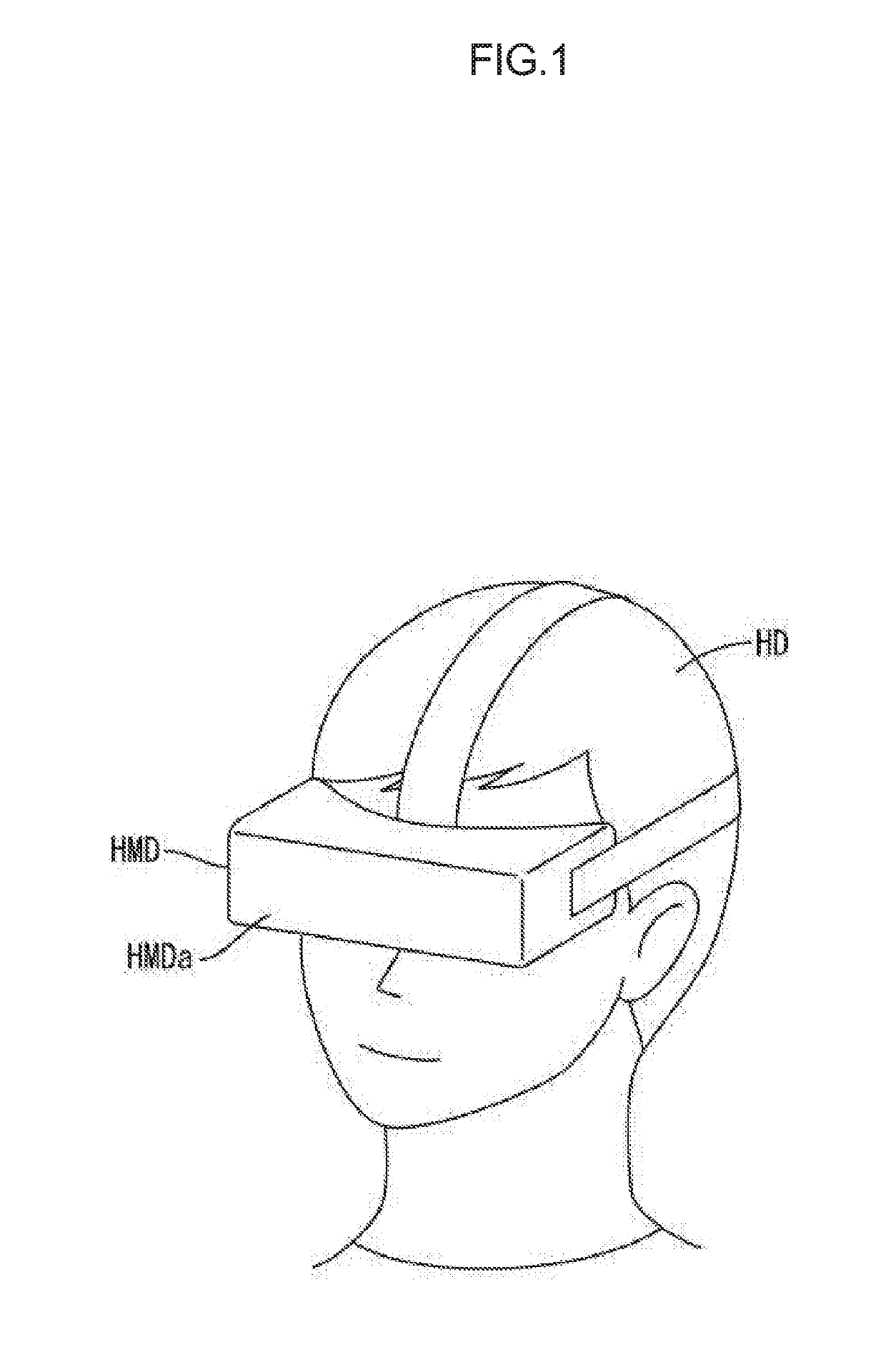
[0025]A first embodiment of the present technology will be described with reference to FIG. 1 to FIG. 4. In the present embodiment, a goggle type head-mounted display (HMD: Head-Mounted Display) HMD and a liquid crystal display device 10 used in the head-mounted display HMD are exemplarily described. In part of each figure, an X axis, a Y axis, and a Z axis are illustrated, so that the illustration in each figure is shown in accordance with the axes.

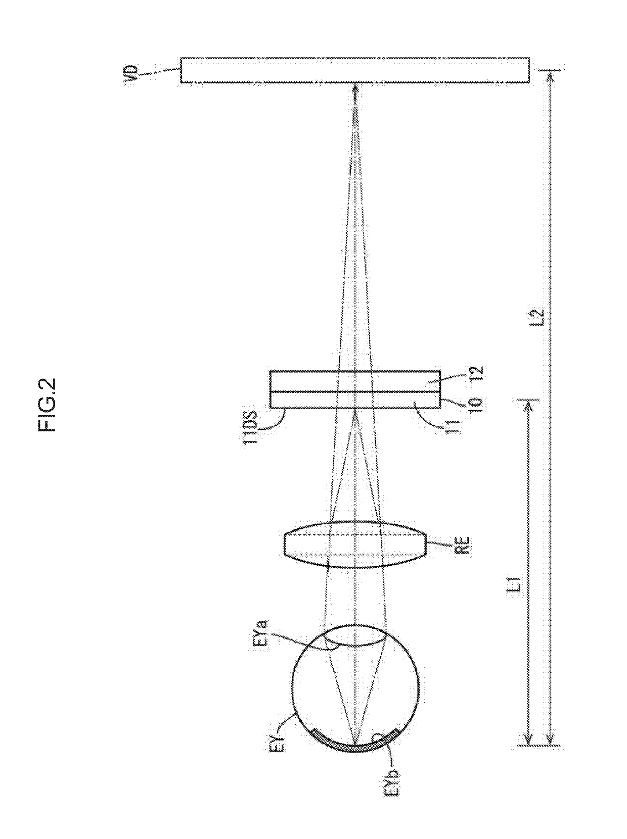
[0026]As shown in FIG. 1, the goggle type head-mounted display HMD is provided with a head-mounted instrument HMDa mounted to a head HD so as to cover both eyes of a user. As shown in FIG. 2, the head-mounted instrument HMDa is provided with at least the liquid crystal display device 10 that displays an image, and a lens portion RE that images the image, which is displayed on the liquid crystal display device 10, in an eyeball EY of a user. The liquid crystal display device 10 is provided with at least a liquid crystal panel 11, and a ba...

second embodiment

[0049]A second embodiment of the present technology will be described with reference to FIG. 5. In the second embodiment, a configuration in which a frame 118 is modified is described. An overlapped description relating to a configuration, a function and an effect similar to those of the first embodiment, is omitted.

[0050]As shown in FIG. 5, the frame 118 according to the present embodiment is formed to directly support a liquid crystal panel 111 and a diffusion sheet 122. In association with this, in the present embodiment, the fixing member 28 (see FIG. 3 and FIG. 4) described above in the first embodiment is omitted. A front side surface of the frame 118 supports an outer peripheral end portion of the liquid crystal panel 111 from a back side. A diffusion sheet support portion 30 protruded from an inner peripheral surface in a stepped manner is arranged in the frame 118. With the diffusion sheet support portion 30, the outer peripheral end portion of the diffusion sheet 122 can b...

third embodiment

[0051]A third embodiment of the present technology will be described with reference to FIG. 6 or FIG. 7. In the third embodiment, a configuration in which a diffusion sheet 222 is modified from that of the second embodiment described above, is described. An overlapped description relating to a configuration, a function and an effect similar to those of the second embodiment, is omitted.

[0052]As shown in FIG. 6 and FIG. 7, in the diffusion sheet 222 according to the present embodiment, a diffusion layer 227 is arranged at a side of a light exit surface 217B. The diffusion layer 227 corresponds to “an anisotropic diffusion layer” that imparts an anisotropic diffusion effect to light. Specifically, the diffusion layer 227 serving as the anisotropic diffusion layer has a configuration in which cylindrical lenses 31, each of which is formed in a substantially half cylindrical shape extended along the Y axis direction, namely a normal direction of a light incident end surface 215B, are al...


PUM


Abstract

A display device includes a display panel having a display surface and a lighting device that supplies light to the display panel. The lighting device includes a light source, and an optical member having at least a light exit surface through which the light emitted by the light source exits toward the display surface of the display panel. The optical member includes a light refraction portion that imparts an anisotropic refraction effect to at least light rays exiting through an edge section of the light exit surface to be oriented toward a center side of the display surface. The display device further includes a low refraction index layer interposed between the display panel and the optical member, and the low refraction index layer has a refraction index lower than at least a refraction index of the optical member.

Description

CROSS REFERENCE TO RELATED APPLICATION[0001]This application claims priority from U.S. Provisional Application No. 62 / 649,581 filed on Mar. 29, 2018. The entire contents of the priority application are incorporated herein by reference.TECHNICAL FIELD[0002]The present technology described herein relates to a display device and a head-mounted display.BACKGROUND ART[0003]Conventionally, a liquid crystal display device disclosed in Patent Document 1 is known as one example of a liquid crystal display device. The liquid crystal display device disclosed in Patent Document 1 is provided with a liquid crystal display panel, a side light type light source that emits light to the liquid crystal display panel, a concave unit case that stores the liquid crystal display panel and the light source, a spacer arranged to form an air layer having a predetermined thickness between the liquid crystal display panel and the light source, and a first light diffusion member arranged between the spacer and...

Claims


Application Information

Patent Timeline
Patent Type & Authority Applications(United States)
IPC IPC(8): G02B27/01G02B3/08G02B5/02G02B5/30
CPCG02B27/0172G02B5/0205G02B5/3025G02B2027/0123G02B3/08G02F1/133606G02F1/133611G02B5/045G02B19/0014
Inventor KANBAYASHI, YUUICHIUSUKURA, NARUKATOH, HIROMI
Owner SHARP KK
Why Eureka
Try Eureka