Electro-optical device, driving method, and electronic apparatus
Active Publication Date: 2006-12-21
SEIKO EPSON CORP
View PDF2 Cites 12 Cited by
Summary
Abstract
Description
Claims
Application Information
AI Technical Summary
This helps you quickly interpret patents by identifying the three key elements:
Problems solved by technology
Method used
Benefits of technology
Benefits of technology
[0008] An advantage of the invention is that it provides an electro-optical device, a driving method, and an electronic apparatus, which can suppress deterioration of display quality when a phase development driving method is adopted.
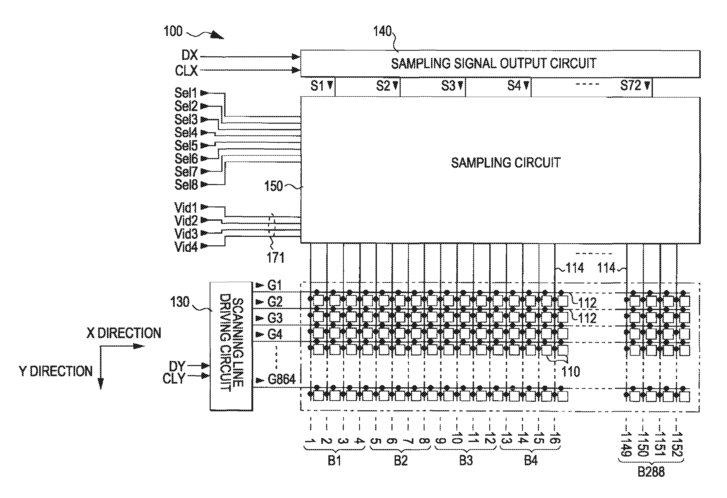
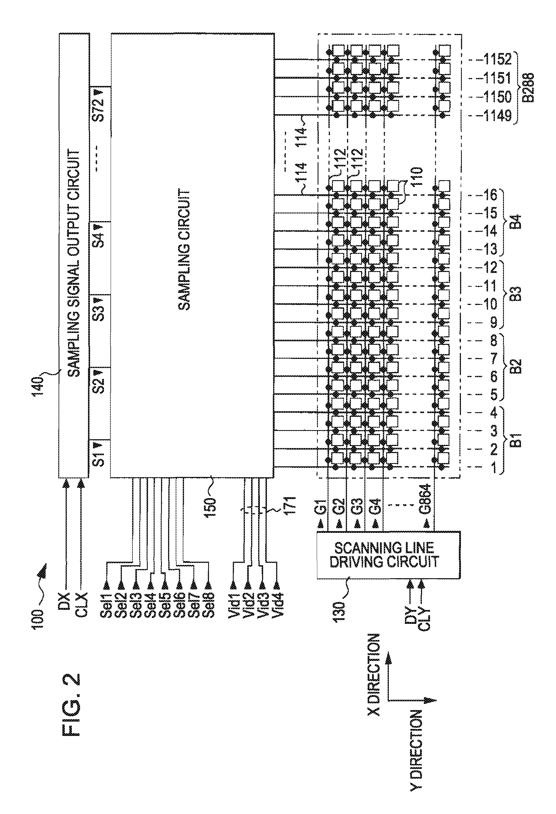
[0009] According to an aspect of the invention, an electro-optical device includes: a plurality of scanning lines, a plurality of data lines blocked for every “m” (m is an integer of 2 or greater) columns, pixels provided corresponding to the scanning lines and the data lines and showing grayscale specified by data signals sampled to data lines when a scanning line is selected, image signal lines, a scanning line driving circuit which selects the scanning line in a predetermined order, a sampling signal output circuit which sequentially outputs a plurality of sampling signals, and a sampling circuit which has a sampling switches for each data lines, and the sampling switches being connected to the corresponding data lines, the sampling circuit turning on the sampling switches to sample data signals supplied to “n” (n is an integer of 2 or greater) of the image signal lines, to the data lines, the blocks being grouped into “n” blocks, individual blocks in the same group corresponding to different image signal lines, and the sampling switches in the individual blocks being connected to corresponding image signal lines, one sampling signal being supplied to two adjacent groups, and when any one sampling signal is supplied, sampling switches in the same columns in “n” blocks belonging to one group of two groups corresponding to the sampling signal are simultaneously turned on. According to the aspect of the invention, it is possible to avoid a state in which the number of times of generation of sampling in adjacent data lines after sampling to data may become fixed.
[0010] In the aspect of the invention, preferably, the sampling circuit turns on sampling switches in any numbered columns in “n” blocks belonging to one group of two groups corresponding to the sampling signal, and thereafter, turns on sampling switches in any numbered columns in “n” blocks belonging to the other group.
[0011] Moreover, the sampling circuit may turn on sampling switches in the same columns in two groups corresponding to the sampling signal, in a predetermined order for every frame by groups over a period in which the sampling signal is supplied and a period in which a sampling signal next to the previous sampling signal is supplied.
[0012] In this configuration, the sampling circuit may turn on the sampling switches according to 2m or more predetermined control signals.
[0013] Furtehrmore, it is desirable that the distributions of the generation frequency of sampling in adjacent data lines after sampling of a data signal during one frame are made equal over individual data lines when at least “m” frames are defined as one cycle.
Problems solved by technology
Therefore, with the progression of high definition, the dot sequential method cannot sufficiently ensure the time taken to supply data signals to the data lines, which results in inadequate write-in to pixels.
Meanwhile, in such a phase development driving method, unevenness in the shape of a vertical stripe that the grayscales of pixels differ delicately every four columns of simultaneous selection is caused, and thereby deterioration of display quality becomes conspicuous.
Method used
Image
Click on the blue label to locate the original text in one second.
Reading with bidirectional positioning of images and text.
Examples
first embodiment
Other Example 1 of First Embodiment
[0151] In the first embodiment, the order that the control signals Sel1 to Sel8 are set to an H level, i.e., that is, the order that columns in individual blocks belonging to adjacent groups are selected are selected is as follows:
[0152] in the first frame, 1st time: Sel5→2nd time: Sel2→3rd time: Sel3→4th time: Sel4→5th time: Sel1→6th time: Sel6→7th time: Sel7→8th time: Sel8;
[0153] in the second frame, 1st time: Sel6→2nd time: Sel3→3rd time: Sel→4th time: Sel1→5th time: Sel2→6th time: Sel7→7th time: Sel8→8th time: Sel5;
[0154] in the third frame, 1st time: Sel7→2nd time: Sel4→3rd time: Sel1→4th time: Sel2→5th time: Sel3→6th time: Sel8→7th time: Sel5→8th time: Sel6; and,
[0155] in the fourth frame, 1st time: Sel8→2nd time: Sel1→3rd time: Sel2→4th time: Sel3→5th time: Sel4→6th time: Sel5→7th time: Sel6→8th time: Sel7. However, the above order is not limited thereto but may also be the following order.
[0156] That is, by exchanging the 2nd time and ...
second embodiment
[0167] Next, an electro-optical device (m=3, n=4) according to a second embodiment of the invention will be described.
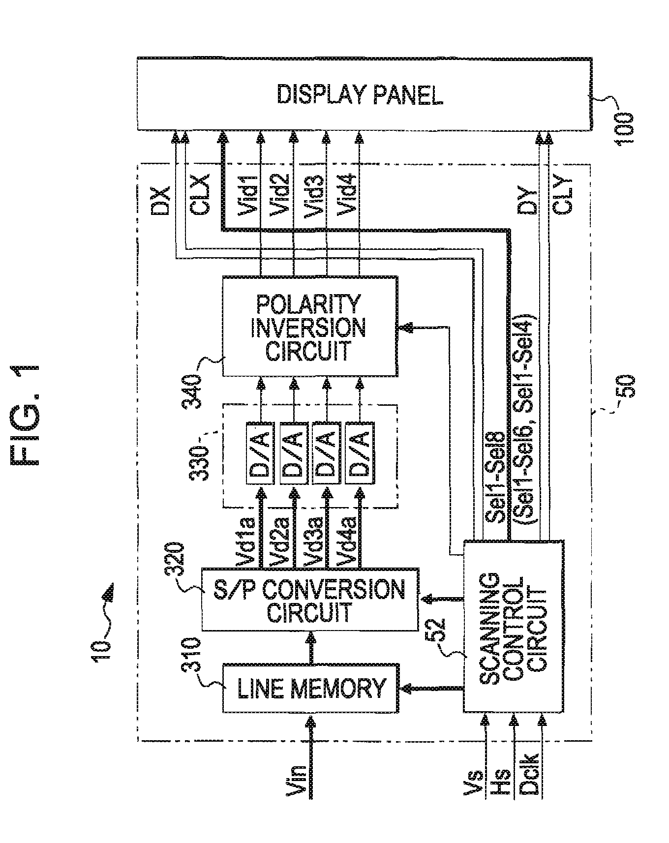
[0168] In this second embodiment, the control signals Sel1 to Sel6 are adopted in the display panel 100 as shown in FIG. 23, and the sampling circuit 150 is configured as shown in FIG. 24. Moreover, in the second embodiment, the scanning control circuit 52 outputs the control signals Sel1 to Sel6, as shown on the left in parentheses of FIG. 1.
[0169] Now, as shown in FIGS. 23 and 24, the second embodiment differs in blocks and groups from the first embodiment. In addition, in the second embodiment, the data lines 114 of 1152 columns are blocked every three columns. Therefore, 1st, 2nd, 3rd, . . . , and 384th blocks when being numbered from the left are denoted by B1, B2, B3, . . . , and B384, respectively.
[0170] In addition, as shown in FIG. 24, grouping is the same as that of the first embodiment in that the grouping is performed every four blocks. In addition, in...
third embodiment
[0186] Subsequently, an electro-optical device (m=2, n=4) according to a third embodiment of the invention will be described.
[0187] In this third embodiment, the control signals Sel1 to Sel4 are adopted in the display panel 100 as shown in FIG. 31, and the sampling circuit 150 is configured as shown in FIG. 32. Moreover, in the third embodiment, the scanning control circuit 52 outputs the control signals Sel1 to Sel6, as shown on the right in parentheses of FIG. 1.
[0188] Now, as shown in FIGS. 31 and 32, the third embodiment differs in blocks and groups from the first and second embodiments. In addition, in this embodiment, the data lines 114 of 1152 columns are blocked every two columns. Therefore, 1st, 2nd, 3rd, . . . , and 576th blocks when being numbered from the left are denoted by B1, B2, B3, . . . , and B576, respectively.
[0189] In addition, as shotgun in FIG. 32, grouping is the same as those of the first and second embodiments in that the grouping is performed every four...
PUM
Abstract
An electro-optical device includes: a plurality of scanning lines; a plurality of data lines blocked for every “m” (m is an integer of 2 or greater) columns; pixels provided corresponding to the scanning lines and the data lines and showing grayscale specified by data signals sampled to data lines when a scanning line is selected; a scanning line driving circuit which selects the plurality of scanning lines in a predetermined order; a sampling signal output circuit which sequentially outputs a plurality of sampling signals; and a sampling circuit which has sampling switches provided in the data lines, respectively, and having their one ends connected to the data lines, and which turns on the sampling switches to sample data signals supplied to “n” (n is an integer of 2 or greater) image signal lines, to the data lines. The sampling circuit groups the blocks for every “n” blocks, makes individual blocks in the same group correspond to different image signal lines, respectively, to connect the other ends of the sampling switches in the individual blocks to corresponding image signal lines, supplies one sampling signal to two adjacent groups, and when any one sampling signal is supplied, simultaneously turns on sampling switches in the same columns in “n” blocks belonging to one group of two groups corresponding to the sampling signal.
Description
BACKGROUND [0001] 1. Technical Field [0002] The invention relates to a technique of suppressing deterioration of display quality when so-called phase-developed data signals are sampled. [0003] 2. Related Art [0004] In recent years, projectors in which a small reduced image is formed using a display panel of liquid crystal or the like, and this small reduced image is enlarged and projected by an optical system have come into wide spread. The projectors themselves have no function to create images, and receive image data (or image signals) from host apparatuses, such as a personal computer and a television tuner. Since this image data which specifies the grayscale (brightness) of pixels is supplied in a format in which the pixels arrayed in a matrix is scanned vertically and horizontally, display panels used for the projectors also are appropriately driven according to this format. Therefore, the display panels used for the projectors generally are driven by a dot sequential method in...
Claims
Application Information
Patent Timeline
Application Date:The date an application was filed.
Publication Date:The date a patent or application was officially published.
First Publication Date:The earliest publication date of a patent with the same application number.
Issue Date:Publication date of the patent grant document.
PCT Entry Date:The Entry date of PCT National Phase.
Estimated Expiry Date:The statutory expiry date of a patent right according to the Patent Law, and it is the longest term of protection that the patent right can achieve without the termination of the patent right due to other reasons(Term extension factor has been taken into account ).
Invalid Date:Actual expiry date is based on effective date or publication date of legal transaction data of invalid patent.

