Electroluminescent display

A luminescent and display technology, applied in the field of electroluminescent displays, can solve problems such as high driving current

Active Publication Date: 2016-06-29
SAMSUNG DISPLAY CO LTD
View PDF5 Cites 11 Cited by
  • Summary
  • Abstract
  • Description
  • Claims
  • Application Information

AI Technical Summary

Problems solved by technology

Therefore, as the brightness of the displayed im

Method used


Image

  • Electroluminescent display
  • Electroluminescent display
  • Electroluminescent display

Examples


Embodiment Construction

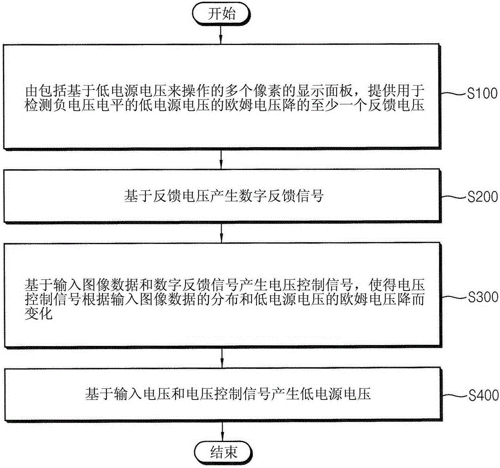
[0069] In an electroluminescent display, the drive current flowing through the OLEDs in the pixels increases as the drive voltage increases, wherein the drive voltage corresponds to the difference between the high supply voltage and the low supply voltage. As the driving voltage increases, the quality of a displayed image can be improved but power consumption increases.

[0070] Hereinafter, example embodiments are described more fully with reference to the accompanying drawings. The same or similar reference numerals denote the same or similar elements throughout. In this disclosure, the term "substantially" includes the following meanings: completely, almost completely, or any significant degree in certain applications according to those skilled in the art. Furthermore, "formed on" can also mean "formed over". The term "connected" may include electrical connections.

[0071] figure 1 is a flowchart illustrating a driving method of an electroluminescence display according...


PUM


Abstract

An electroluminescent display (10) and a method of driving the same are disclosed. In one aspect, the display includes a display panel (40) including a plurality of pixels (PX) configured to operate based on a first power supply voltage (ELVSS) having a negative voltage level. The display panel (40) is configured to generate at least one feedback voltage (VFB) corresponding to an ohmic drop (IRD) of the first power supply voltage (ELVSS). An analog-to-digital converter (50) is configured to generate at least one digital feedback signal (DG_VFB) based on the at least one feedback voltage (VFB). An adaptive voltage controller (20) is configured to generate a voltage control signal (DG_ELVSS) based on input image data (RGB_DATA), the at least one digital feedback signal (DG_VFB), a distribution of the input image data and the ohmic drop (IRD) of the first power supply voltage (ELVSS). A voltage converter (30) is configured to generate the first power supply voltage(ELVSS) based on an input voltage (VIN) and the voltage control signal (DG_ELVSS).

Description

technical field [0001] The technology described generally relates to electroluminescent displays and methods of driving electroluminescent displays. Background technique [0002] Various display devices, such as liquid crystal displays (LCDs), plasma displays, and electroluminescence displays, have become popular. Among these display devices, an electroluminescent display can be driven with a fast response speed and reduced power consumption using a matrix of light emitting diodes (LEDs) or organic light emitting diodes (OLEDs) that emit light through recombination of electrons and holes. Each OLED includes an anode electrode, a cathode electrode, and a light emitting layer between the two electrodes, the light emitting layer being formed of a material that emits light according to a driving current flowing from the anode electrode through the light emitting layer to the cathode electrode. The brightness of the electroluminescent display is determined by the drive current o...

Claims


Application Information

Patent Timeline
IPC IPC(8): G09G3/3208
CPCG09G3/3233G09G2330/028G09G2360/16G09G3/30G09G3/32Y02B20/30G09G3/2018G09G3/2003G09G3/3258G09G2300/0426G09G2310/08G09G2320/0626G09G2330/021G09G2310/027G09G2300/0819H10K59/131
Inventor 朴修亨徐志明郑喜顺尹铢浣郑智雄洪准佑高俊哲
Owner SAMSUNG DISPLAY CO LTD
Why Eureka
Try Eureka