Head-mounted display apparatus

a display apparatus and head-mounted technology, applied in the field of head-mounted display apparatuses, can solve the problems of troublesome removal of the spectacle prior to each movement, screen becomes a stress factor for the observer, and may disturb the ordinary movement, so as to achieve the effect of effectively reducing the power consumption

Active Publication Date: 2007-04-03
OLYMPUS CORP
View PDF5 Cites 378 Cited by
  • Summary
  • Abstract
  • Description
  • Claims
  • Application Information

AI Technical Summary

Benefits of technology

[0013]Accordingly, it is an object of the present invention to provide a head-mounted display apparatus in which the observation of an image and that of the external environment can be simply changed over, and also the power consumption can be effectively reduced.

Problems solved by technology

However, when the brightness is low, the pyramids do not effectively act, so that the difference between the visual acuities in the center and in the periphery is not significant.
Particular, when the observer wears the device for a long time, the screen becomes a factor in stress to the observer.
However, if the display screen continues to be displayed in the field of sight of the observer, the screen may disturb the ordinary movement.
However, in the case of the spectacle as an example, it is troublesome to take off the spectacle prior to each movement.
Similarly, it is troublesome to remove the display apparatus or switch off the power supply of the apparatus every time the ordinary movement is made.
However, it is troublesome to frequently switch off the power supply.
It is unsuitable to apply the above-described technique for reducing the consumption power used in personal computers, that is, the technique by which the power supply is controlled in the case in which input-operation is not executed for a predetermined time-period, to information display apparatuses for which intentional input-operation is not necessarily carried out.

Method used


Image

  • Head-mounted display apparatus
  • Head-mounted display apparatus
  • Head-mounted display apparatus

Examples


first embodiment

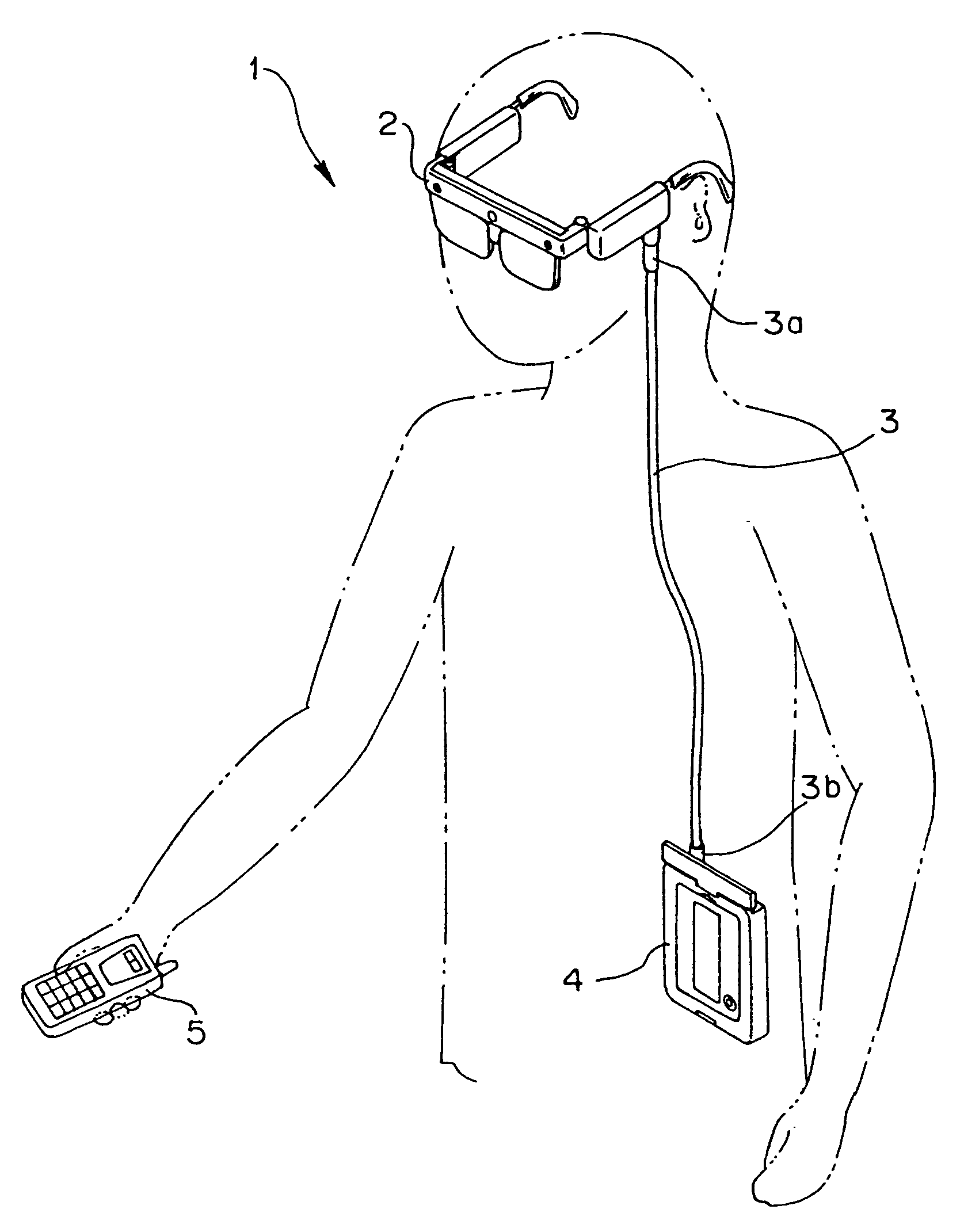
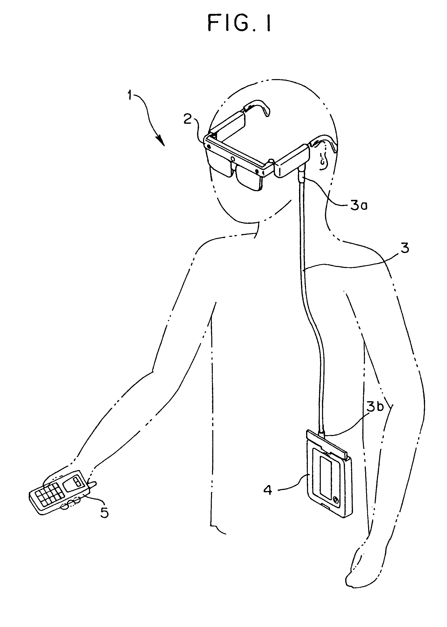
[0051]FIGS. 1 to 33 illustrate an embodiment of the present invention. FIG. 1 is a perspective view illustrating a state in which a head-mounted information display apparatus is used.

[0052]The head-mounted information display apparatus of this embodiment is an information display apparatus of a head-mounted type (a head-mounted information display apparatus), as described below.

[0053]The information display apparatus 1 includes, as shown in FIG. 1, a head-mounted unit 2 formed substantially in the shape of a pair of spectacles, a controller / recorder 4, which serves as the main body of the information display apparatus 1, connected to the head-mounted unit 2 via connecting means, such as a cable 3, and a remote controller 5 for remotely performing input operations for the information display apparatus 1.

[0054]The head-mounted unit 2 allows a user to observe a subject (in the external environment) substantially directly in a see-through display mode and also to observe a piece of info...


PUM

PropertyMeasurementUnit
angle detectoraaaaaaaaaa
tilting angleaaaaaaaaaa
angleaaaaaaaaaa

Abstract

A head-mounted display apparatus comprises a see-through image display portion for setting a display frame in a display-capable range, and displaying an image in such a manner that the image is superimposed on an image of the external environment in the display frame, an angular velocity sensor for detecting the tilting angle of the head of an observer; an LCD driver, a second CPU and the like which control the display frame to move in an amount corresponding to the angle detected by the angle detection means in the direction opposite to the tilting direction of the observer's head, whereby the position of a virtual image, observed by the observer, is kept substantially constant, irrespective of the tilting of the observer's head, and first CPU which controls the apparatus so that the mode of the apparatus is automatically changed to a low consumption power mode.

Description

[0001]This application claims benefit of Japanese Application No. 2004-137768 filed in Japan on May 6, 2004, Japanese Application No. 2004-174564 filed in Japan on Jun. 11, 2004, the contents of which are incorporated by this reference.BACKGROUND OF THE INVENTION[0002]1. Field of the Invention[0003]The present invention relates to a head-mounted display apparatus, and more particularly, to a head-mounted display apparatus which displays images in a manner such that they can be observed while wearing the apparatus on one's head.[0004]2. Description of the Related Art[0005]Hitherto, display apparatuses which are mounted to heads and by which images are observed, such as HMD (Head-Mounted Display) and HUD (Head-Up Display) have been known.[0006]This type of display apparatuses are described, for example, in Japanese Unexamined Patent Application Publication No. 2003-248194. In the image display apparatus described in the Publication, an image disposed on a spectacle frame is projected ...

Claims


Application Information

Patent Timeline
Patent Type & Authority Patents(United States)
IPC IPC(8): G02B27/14G09G5/00G02B27/00G02F1/13G02B27/01G02B27/02G06F1/16G06F1/32G06F3/00G06F3/01H04N5/64
CPCG02B27/0093G02B27/017G06F3/012G02B2027/014G02B2027/0187
Inventor YAMASAKI, MASAFUMI
Owner OLYMPUS CORP
Why Eureka
Try Eureka