Display device, drive circuit thereof, driving method therefor, and electronic equipment

a technology of drive circuit and display device, which is applied in the direction of electric digital data processing, instruments, computing, etc., can solve the problems of high voltage switching frequency, deterioration of display quality, waste of electric power, etc., and achieve the effect of reducing power consumption or the like and preventing the degradation of display quality

Inactive Publication Date: 2007-03-27
SEIKO EPSON CORP
View PDF7 Cites 12 Cited by
  • Summary
  • Abstract
  • Description
  • Claims
  • Application Information

AI Technical Summary

Benefits of technology

[0011]The present invention has been made in view of the above, and an object of the present invention is to provide a display device, a drive circuit thereof, a driving method therefor, and electronic equipment that achieves reduced power consumption while restraining degradation in display quality.
[0032]Electronic equipment according to the present invention is equipped with the aforesaid display device, thus permitting reduced power consumption or the like to be achieved, while restraining the degradation in display quality. Such electronic equipment includes a personal computer, a cellular telephone, a digital still camera and the like.

Problems solved by technology

However, performing the intermediate gray scale display in the above four-value driving method inevitably leads to a higher voltage switching frequency of data lines, thus posing a shortcoming in that electric power is wasted due to capacitance accompanying the data lines.
On the other hand, if the four-value driving method (½H selection, 1H inversion) is not used, then a problem occurs in which display quality is deteriorated, depending upon a mode.

Method used


Image

  • Display device, drive circuit thereof, driving method therefor, and electronic equipment
  • Display device, drive circuit thereof, driving method therefor, and electronic equipment
  • Display device, drive circuit thereof, driving method therefor, and electronic equipment

Examples


Embodiment Construction

[0069]An embodiment of the present invention will now be explained with reference to the accompanying drawings.

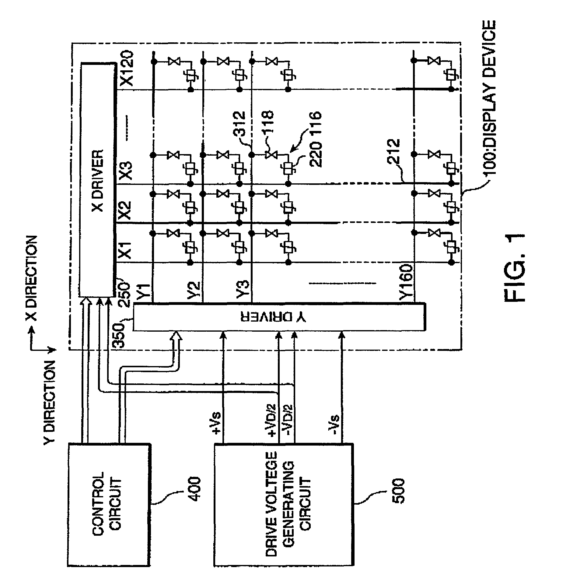
[0070]First, an electrical construction of the display device in accordance with the embodiment of the present invention will be explained. FIG. 1 is an exemplary block diagram showing the construction.

[0071]As shown in the diagram, in a display device 100, a plurality of data lines (segment electrodes) 212 are formed such that they extend in a column (Y) direction, while a plurality of scanning lines (common electrodes) 312 are formed such that they extend in a line (X) direction, and pixels 116 are formed for the individual intersections of the data lines 212 and the scanning lines 312. Furthermore, each of the individual pixels 116 can be formed of a liquid crystal capacitor 118 and a TFD (Thin Film Diode) 220, which is an example of a two-terminal type switching element, that are connected in series. Of these, the liquid crystal capacitor 118 is constructed such that a ...


PUM

PropertyMeasurementUnit
poweraaaaaaaaaa
holding voltage Vhldaaaaaaaaaa

Abstract

The present invention provides a drive circuit of a display device that reduces power consumption while restraining the occurrence of cross talk at the same time. The drive circuit can include a plurality of scanning lines that are bundled into a block, and the polarities of the selection voltages of scanning signals Yi, Yi+1, Yi+2, and Yi+3 supplied to the scanning lines that belong to the same block are alternately inverted. Furthermore, the polarity of the selection voltage of the scanning signal Yi+3 supplied to the scanning line selected last in the block is the same as the polarity of the selection voltage of the scanning signal Yi+4 supplied to the scanning line selected first in a block following the aforesaid block. Accordingly, it is possible to reduce power consumption while restraining the degradation in display quality at the same time.

Description

BACKGROUND OF THE INVENTION[0001]1. Field of Invention[0002]The present invention relates to a display device, a drive circuit thereof, and a driving method therefor. The invention further relates to electronic equipment that achieve reduced power consumption while restraining degradation in display quality in, for example, device where the switching of pixels is performed by a thin film diode.[0003]2. Description of Related Art[0004]Currently, display units making use of electro-optical changes of liquid crystals are being extensively used with a variety of electronic equipment, such as televisions, and the like, as display devices that replace cathode ray tubes (CRT) by taking advantage of their features, such as thin compact designs and lower power consumption.[0005]The display devices may be roughly divided on the basis of a driving system or the like into an active matrix type in which pixels are driven by switching and a passive matrix type in which pixels are driven without u...

Claims


Application Information

Patent Timeline
Patent Type & Authority Patents(United States)
IPC IPC(8): G09G5/00G02F1/1343G02F1/133G02F1/1365G09G3/20G09G3/36
CPCG09G3/3674G09G3/3685G09G3/367G09G3/2014G09G3/3614G09G2320/0209
Inventor YAMAZAKI, KATSUNORI
Owner SEIKO EPSON CORP
Why Eureka
Try Eureka