Ignition device, internal combustion engine and method for its operation

a technology of internal combustion engine and ignition device, which is applied in the direction of engine ignition, electric ignition installation, engine ignition, etc., can solve the problems of generator only providing battery may be drained, and generator provides only a comparatively low voltage and/or power, so as to achieve safe load operation and high energy demand

Active Publication Date: 2019-11-07
PRUFREX ENG E MOTION
View PDF7 Cites 1 Cited by
  • Summary
  • Abstract
  • Description
  • Claims
  • Application Information

AI Technical Summary

Benefits of technology

The objective of this patent is to create an effective ignition system that can safely operate both an electric load and an internal combustion engine simultaneously without causing any damage or malfunctions. This includes providing sufficient power to start up the vehicle's motor while still being able to handle other necessary functions like running lights and air conditioning. Additionally, there will be no delay when switching from one mode (electric) to another (engine).

Problems solved by technology

The technical problem addressed in this patent relates to supplying electricity to loads with higher energy demands than traditional batteries or generators when operating implements, like chainsaws or mowers, that use low power engines. These low power engines require a separate ignition system to generate an ignition spark, leading to reduced efficiency and increased emissions. Additionally, these engines have slow start-up times compared to other types of engines, making them difficult to operate without releasing excessive wear and tear on equipment.

Method used


Image

  • Ignition device, internal combustion engine and method for its operation
  • Ignition device, internal combustion engine and method for its operation
  • Ignition device, internal combustion engine and method for its operation

Examples


Embodiment Construction

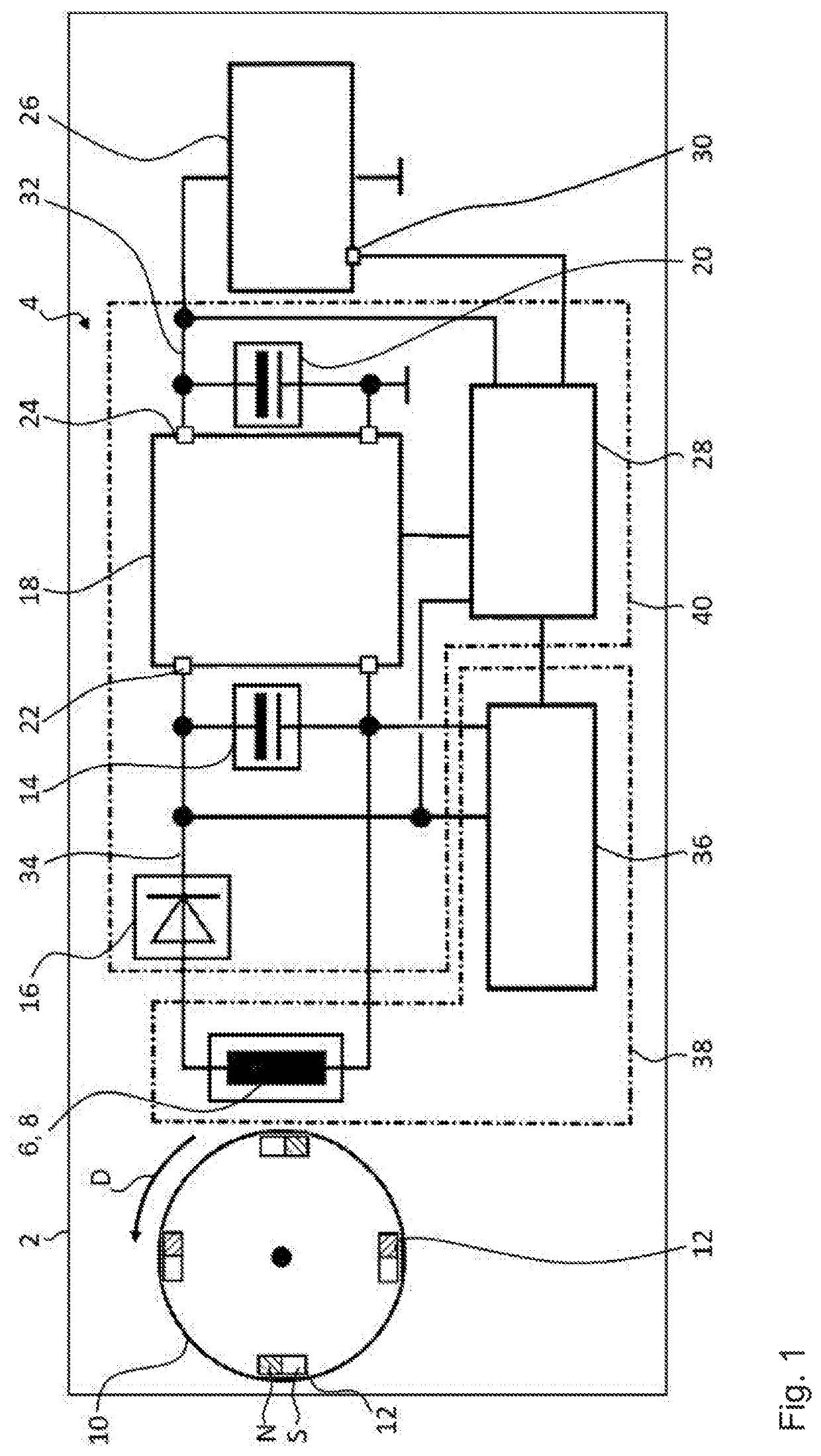
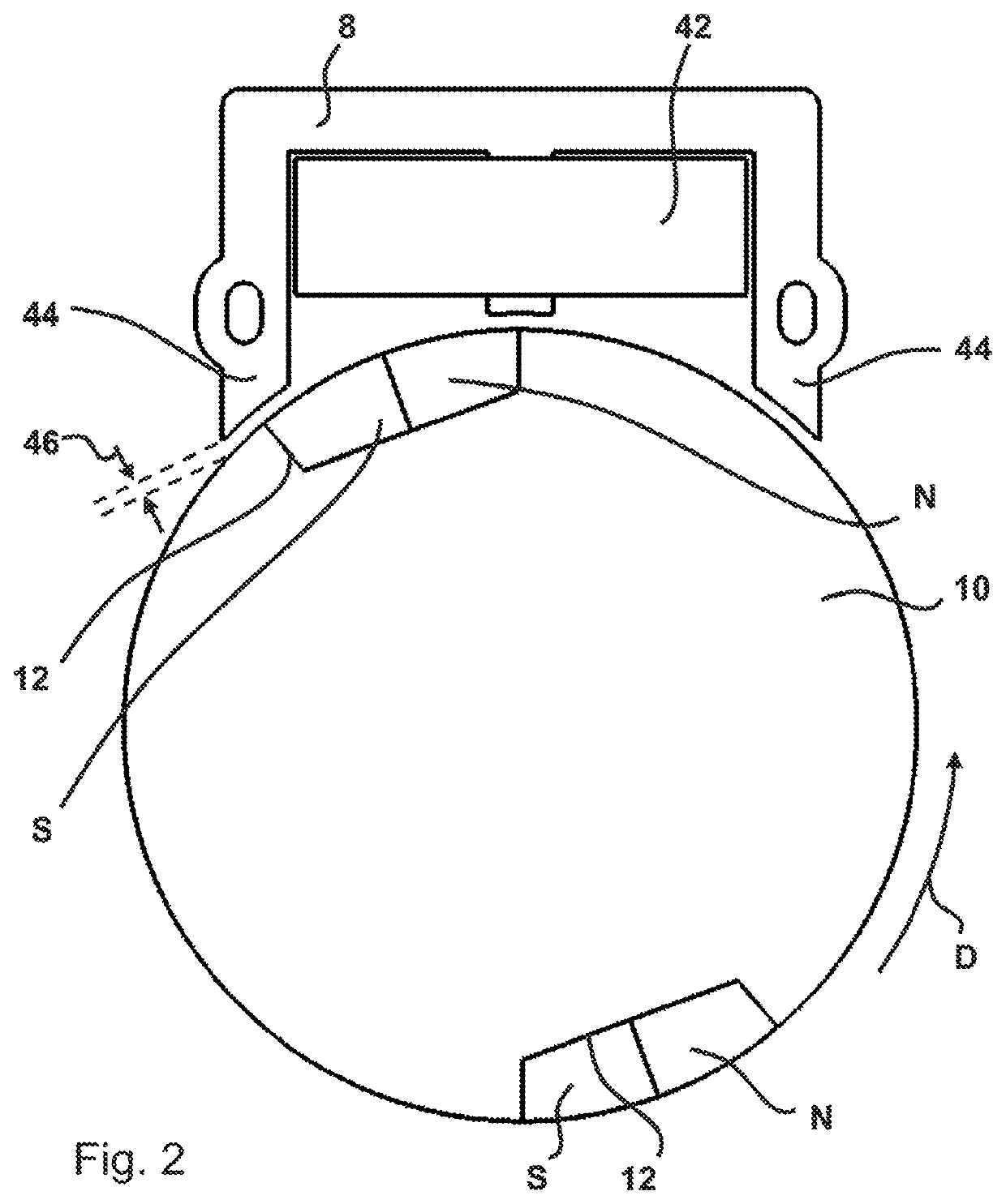
[0053]FIG. 1 shows an internal combustion engine 2 with an ignition device 4. A method B for its operation is shown as a flow chart in FIG. 4. The ignition device has a charging coil 6 which is arranged on a yoke core 8 designed as an iron core. Furthermore, the internal combustion engine 2 has a starter wheel 10 which is rotatable in a direction of rotation D, which in this case is a flywheel with four magnets 12. At a rotation of the starter wheel 10, the magnets 12 of the starter wheel 10 are moved past the charging coil 6 so that a charging voltage UL is induced in the charging coil 6, which has temporally consecutive positive and negative half waves.

[0054]Further, one of the magnets 12, hereinafter referred to as a magnetic position sensor, is arranged such that upon rotation of the starter wheel in the direction of rotation D, first its north pole N is moved past the charging coil 6, and then its south pole S. The other magnets 12 are oppositely arranged, i.e., at a at rotatio...


PUM


Abstract

An ignition device for an internal combustion engine with a charging coil, in particular disposed on a yoke core, with a starter wheel to induce a charging voltage in the charging coil by its rotation, with a first energy store which is connected to the charging coil via a rectifier, as well as with an electrical load which for its power supply, in particular during the starting process of the internal combustion engine is connected to a second energy store, wherein the second energy store is connected to the first energy store via a voltage converter. Furthermore, the invention relates to an internal combustion engine with such an ignition device and a method for its operation.

Description


Claims


Application Information

Patent Timeline
Owner PRUFREX ENG E MOTION
Why Eureka
Try Eureka