Fully variable and integral aeration flap controller

A valve, variable technology, used in transportation and packaging, heating/cooling equipment, air handling equipment, etc.

Pending Publication Date: 2021-02-26
BAYERISCHE MOTOREN WERKE AG
View PDF8 Cites 1 Cited by
  • Summary
  • Abstract
  • Description
  • Claims
  • Application Information

AI Technical Summary

Problems solved by technology

It is therefore particularly disadvantageous that the vehicle occupants are not always optimally air-conditioned or are distracted by the manual configuration of the air-conditioning system

Method used


Image

  • Fully variable and integral aeration flap controller

Examples


Embodiment Construction

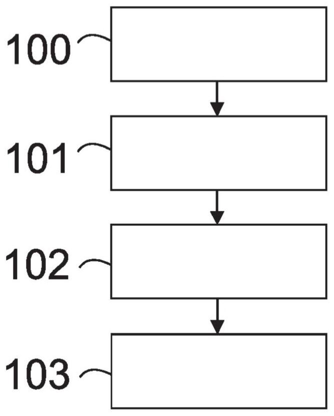
[0037] figure 1 A method for automatically and fully variable control of ventilation valves in a vehicle is shown in a schematic flow chart, characterized in that: reading 100 the position of the ventilation valves for each ventilation outlet; providing 101 a plurality of ventilation valves configurations of positions, wherein each configuration assigns a generated noise level and a generated energy demand to each combination of ventilation valve positions; assigns 102 a weight between the noise level and the energy demand; and assigns 102 weights between the assigned 102 weights Adjust the vent valve position for each read 103.

[0038] According to another aspect, figure 1 Shown is a method for automatic and fully variable control of ventilation valves in a vehicle, characterized by: reading 100 ratings of the valve position or intensity of air flow for each ventilation outlet; providing 101 more than one ventilation configurations of valve positions, wherein each configur...


PUM


Abstract

The invention relates to a method and system for controlling an aeration flap automatically and in a fully variable manner in a vehicle, comprising the following steps: - reading (100) a target valuefor a flap position or strength of an airflow of each aeration outlet; - providing (101) a plurality of configurations of aeration flap positions, wherein each configuration assigns a resultant noiselevel and a resultant energy demand for each combination of aeration flap positions; - specifying (102) a weighting between noise level and energy demand; and - adapting each of the read (103) targetvalues for a flap position or strength of an airflow according to the specified (102) weighting. Amongst other things, the development of noise in the vehicle may be influenced advantageously as a result.

Description

technical field [0001] The invention relates to a method for actuating a ventilation valve control. In this way, in particular the generation of noise in the vehicle can be influenced in an advantageous manner. The invention also relates to a correspondingly designed system arrangement. Furthermore, a computer program product is proposed which has control instructions which carry out the method or operate the proposed system arrangement. Background technique [0002] EP1236593A2 shows an air-conditioning device with a device for regulating thermal comfort in a motor vehicle, which device has at least one temperature sensor and an outflow device for directing the outflow of air into an outflow area, which features This consists in that the measuring surface detected by the temperature sensor approximately corresponds to the air inflow surface predetermined by the orientation of the outflow device. [0003] EP0419722A1 shows an air conditioning system for ventilating the pa...

Claims


Application Information

Patent Timeline
Patent Type & Authority Applications(China)
IPC IPC(8): B60H1/00
CPCB60H1/00842B60H1/00971B60H1/00742B60H1/00778B60H1/00392B60H1/00871B60H1/004
Inventor S·奥伯贝格R·赫博尔茨海默A·克罗姆帕斯T·霍恩斯泰格M·瓦克尔宾格
Owner BAYERISCHE MOTOREN WERKE AG
Why Eureka
Try Eureka