A kind of ups power supply for oil field production equipment

A technology for oil production equipment and oil fields, which is applied in the substation/distribution device casing, cooling/ventilation of substation/switchgear, electrical components, etc. The difficulty of disassembly and installation, the effect of improving the heat dissipation effect, and the effect of improving convenience

Active Publication Date: 2019-10-25
隆赫电气设备有限公司
View PDF5 Cites 0 Cited by
  • Summary
  • Abstract
  • Description
  • Claims
  • Application Information

AI Technical Summary

Problems solved by technology

[0004] The invention provides a UPS power supply for an oil production device in an oil field, which has the advantages of easy disassembly and installation, good heat dissipation effect, and easy filter replacement and cleaning, and solves the problem that the existing UPS power supply is installed inside a power cabinet. During use, the power cabinet is directly placed on a base without fixing, which reduces the stability of the power cabinet. Even if the existing power cabinet is fixed, it is directly fixed by fixing bolts, and tool assistance is required when disassembling the power cabinet. The disassembly and operation are cumbersome, and the power cabinet will generate noise during operation, which easily distracts the staff and reduces work efficiency. At the same time, the power supply will generate heat when it is working. The dust will enter the UPS power cabinet through the heat dissipation holes. The existing power cabinet is not easy to clean the dust, which may easily cause the short circuit of the power cabinet.

Method used


Image

  • A kind of ups power supply for oil field production equipment
  • A kind of ups power supply for oil field production equipment
  • A kind of ups power supply for oil field production equipment

Examples


Embodiment Construction

[0024] The following will clearly and completely describe the technical solutions in the embodiments of the present invention with reference to the accompanying drawings in the embodiments of the present invention. Obviously, the described embodiments are only some, not all, embodiments of the present invention. Based on the embodiments of the present invention, all other embodiments obtained by persons of ordinary skill in the art without making creative efforts belong to the protection scope of the present invention.

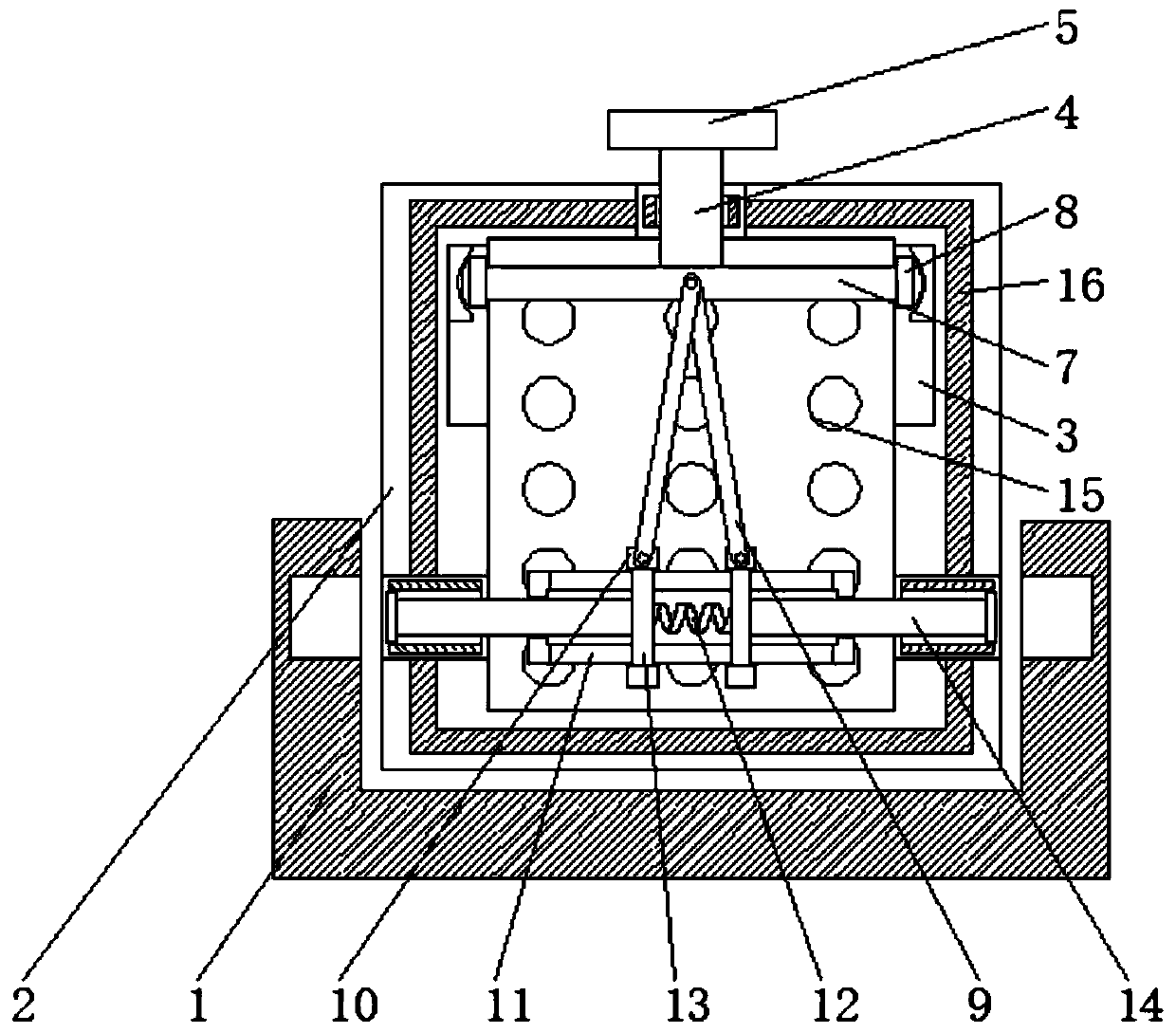
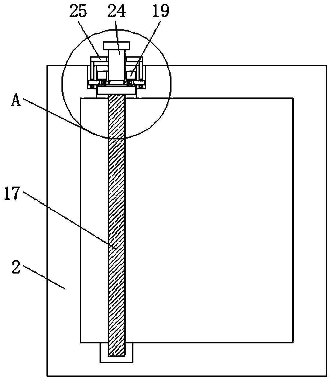
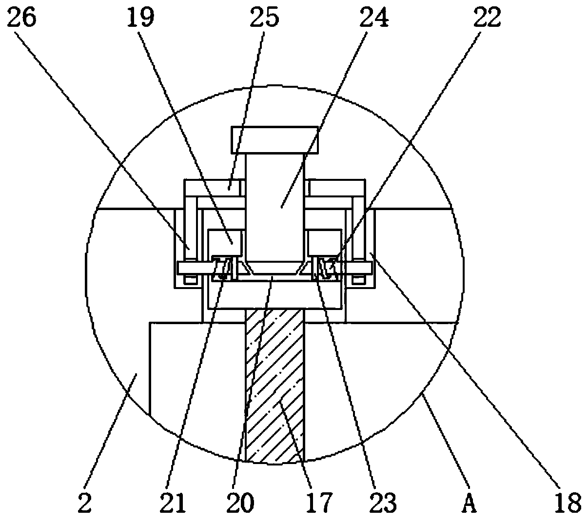
[0025] see Figure 1-4, a UPS power supply for an oil field oil production device, including a base 1, the shape of the base 1 is concave, and the tops on both sides of the inner cavity of the base 1 are respectively provided with card slots, the card slots on the base 1 and the card rod 14 are on the same horizontal line , and the distance between one side of the inner cavity of the card slot on the base 1 and the side of the upper limit block of the card rod...


PUM


Abstract

The invention relates to the technical field of electrical product accessories, and discloses a UPS power supply for an oil extraction device of oil fields. The UPS power supply comprises a base, a UPS power supply cabinet is placed on the top of the base, sliding slots are respectively formed in both sides of the top of an inner cavity of the UPS power supply cabinet, a round bar is movably sleeved at the top of the UPS power supply cabinet, a top end of the round bar passes through and extends to the outside of an upper surface of the UPS power cabinet and is fixedly connected with the bottom of an adjusting button, a bottom end of the round bar passes through and extends to the inside of the UPS power cabinet and is connected with the middle of the top end of a connecting rod, and the two ends of the connecting rod are fixedly connected with the middle of a movable rod. According to the UPS power supply for the oil extraction device of the oil fields, by means of the coaction of theadjusting button and the connecting rod and the cooperative use of a clamping block and an elastic block, a clamping rod is prevented from being popped up from the UPS power cabinet under the actionof the elastic force of a spring, so that the convenience of mounting and fixing the UPS power supply cabinet is improved, and the difficulty of dismounting and mounting the UPS power supply cabinet by manpower is reduced.

Description

technical field [0001] The invention relates to the technical field of electric appliance accessories, in particular to a UPS power supply for an oil production device in an oil field. Background technique [0002] UPS is an uninterruptible power supply. It is a system device that connects batteries (mostly lead-acid maintenance-free batteries) with the host, and converts direct current into mains power through module circuits such as host inverters. It is mainly used for powering single computers and computers. The network system or other power electronic equipment such as solenoid valves, pressure transmitters, etc. provide stable and uninterrupted power supply. [0003] The existing UPS power supply is installed inside a power cabinet. During use, the power cabinet is directly placed on a base without fixing, which reduces the stability of the power cabinet. Even if the existing power cabinet is fixed It is also directly fixed by fixing bolts. When disassembling the powe...

Claims


Application Information

Patent Timeline
Patent Type & Authority Patents(China)
IPC IPC(8): H02B1/30H02B1/54H02B1/56
CPCH02B1/30H02B1/54H02B1/565
Inventor 不公告发明人
Owner 隆赫电气设备有限公司
Why Eureka
Try Eureka