

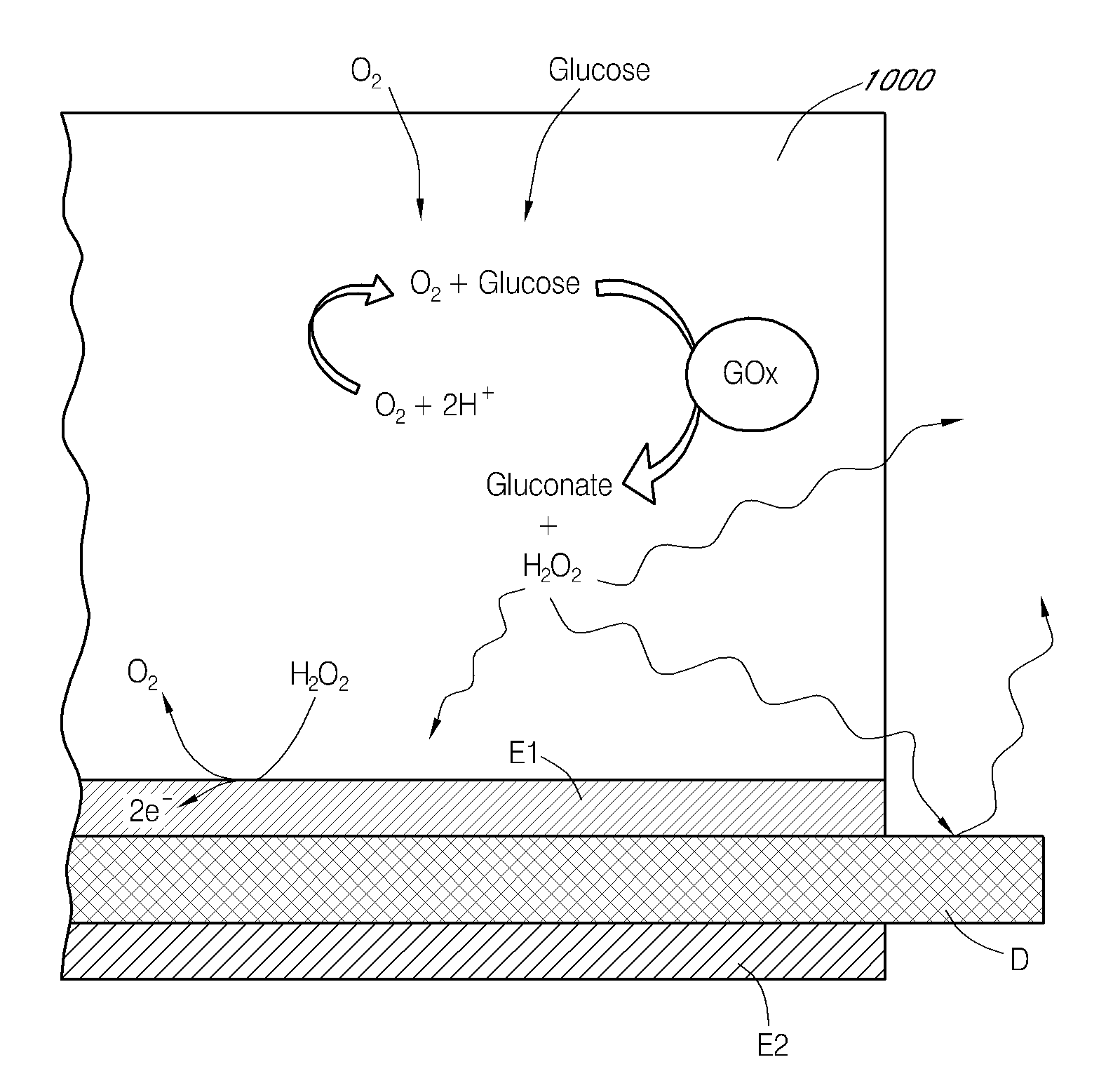
Dual electrode system for a continuous analyte sensor
a technology of continuous analyte and dual electrodes, applied in the field of systems and methods for measuring analyte concentration, can solve the problems of measurable increase or decrease of signal, and achieve the effect of substantial noise-free signal
- Summary
- Abstract
- Description
- Claims
- Application Information
AI Technical Summary
Benefits of technology
Problems solved by technology
Method used
Image

Examples
example 1
Dual-Electrode Sensor with Coiled Reference Electrode
[0491]Dual-electrode sensors (having a configuration similar to the embodiment shown in FIG. 9B) were constructed from two platinum wires, each coated with non-conductive material / insulator. Exposed electroactive windows were cut into the wires by removing a portion thereof. The platinum wires were laid next to each other such that the windows are offset (e.g., separated by a diffusion barrier). The bundle was then placed into a winding machine & silver wire was wrapped around the platinum electrodes. The silver wire was then chloridized to produce a silver / silver chloride reference electrode. The sensor was trimmed to length, and a glucose oxidase enzyme solution applied to both windows (e.g., enzyme applied to both sensors). To deactivate the enzyme in one window (e.g., window 904a, FIG. 9B) the window was dipped into dimethylacetamide (DMAC) and rinsed. After the sensor was dried, a resistance layer was sprayed onto the sensor ...
example 2
Dual-Electrode Sensor with X-Shaped Reference Electrode
[0493]This sensor was constructed similarly to the sensor of Example 1, except that the configuration was similar to the embodiment shown in FIG. 7J. Two platinum electrode wires were dipped into non-conductive material and then electroactive windows formed by removing portions of the nonconductive material. The two wires were then bundled with an X-shaped silver reference electrode therebetween. An additional layer of non-conductive material held the bundle together.
[0494]FIG. 13 shows the results from one experiment, comparing the signals from the two electrodes of a dual-electrode sensor having an X-shaped reference electrode. The “Plus GOx” electrode has active GOx in its window. The “No GOx” electrode has DMAC-inactivated GOx in its window. The sensor was tested as was described for Experiment 1, above. Signal from the two electrodes were substantially equivalent until the sensor was transferred to the 40-mg / dl glucose solu...
example 3
Dual-Electrode Challenge with Hydrogen Peroxide Glucose, and Acetaminophen
[0495]A dual-electrode sensor was assembled similarly to the sensor of Example 1, with a bundled configuration similar to that shown in FIG. 7C (two platinum working electrodes and one silver / silver chloride reference electrode, not twisted). The electroactive windows were staggered by 0.085 inches, to create a diffusion barrier.
[0496]FIG. 14 shows the experimental results. The Y-axis shows the glucose signal (volts) and the X-axis shows time. The “Enzyme” electrode included active GOx. The “No Enzyme” electrode did not include active GOx. The “Enzyme minus No Enzyme” represents a simple subtraction of the “Enzyme” minus the “NO Enzyme.” The “Enzyme” electrode measures the glucose-related signal and the non-glucose-related signal. The “No Enzyme” electrode measures only the non-glucose-related signal. The “Enzyme minus No Enzyme” graph illustrates the portion of the “Enzyme” signal related to only the glucose-...
PUM
| Property | Measurement | Unit |
|---|---|---|
| Length | aaaaa | aaaaa |
| Pore size | aaaaa | aaaaa |
| Flow rate | aaaaa | aaaaa |
Abstract
Description
Claims
Application Information