Oral hydration system

a hydration system and oral technology, applied in the field of oral hydration system, can solve the problems of people being particularly vulnerable to dehydration, constant concern and problem of dehydration, and having a hard time staying adequately hydrated, so as to maintain proper hydration, reduce the mobility of individuals or strength, and improve the effect of hydration

Inactive Publication Date: 2020-08-20
HADEN JIM
View PDF0 Cites 2 Cited by
  • Summary
  • Abstract
  • Description
  • Claims
  • Application Information

AI Technical Summary

Benefits of technology

[0012]The invention addresses the above deficiencies and provides related benefits. In particular, it is an object of the invention to provide a more efficient and safe method for an individual to maintain proper hydration. In particular, when mobility of the individual or strength is lessened.
[0013]In one aspect of the invention an oral hydration system is provided, which includes a fluid reservoir; a supply tube fluidly coupled to the reservoir at its distal end; and a mouthpiece pump molded as a single piece utilizing one pliable material and deformable along its entire length. The mouthpiece pump is preferably fluidly coupled at its distal end to a proximal end of the supply tube. Preferably, the mouthpiece pump or the supply tube has a one-way distal valve, and the mouthpiece pump is sealed proximally with a proximal face in a form of a mouthpiece containing a proximal valve that seals until the pump is deformed by a user for the purpose of creating a priming and pumping action to draw fluid from the reservoir, through the supply tube and out of the mouthpiece pump to the user. Preferably, the mouthpiece pump can be safely compressed or bitten at any portion of the mouthpiece pump without risk of biting or dislodging a rigid or secondary piece.
[0015]The mount improves user access to the hydration system by permitting the mounting of the hydration system to a variety of structures. In the medical industry the mount is particularly useful for bed rails, back of a chair, or wheelchair. Preferably, the one or more mounts are reversibly bendable yet remain sufficiently rigid to support the hanging weight of a reservoir, filled with liquid, in a straightened orientation extending perpendicularly from the reservoir and compressed between objects such as a bed mattress and frame. Furthermore, the bendable yet semi rigid nature of the one or more mounts allow the reservoir to be adjusted in a vertical orientation when attached to an inclined or angled structure such as a hospital bed. In some embodiments, one or more mounts are co-molded or bonded to the reservoir. However, in other embodiments the one or more mounts are releasably attached to reservoir.
[0018]In another related aspect, the invention also provides a hydration system, which includes a fluid reservoir having a means for reversibly mounting the hydration system to a structure; a supply tube fluidly coupled to the reservoir at its distal end; a reversibly compressible chamber fluidly coupled to the supply tube; a mouthpiece proximate to or at a proximal end of the collapsible chamber; and at least two valves that, together with the chamber, regulate the flow of fluid through the hydration system, wherein a distal valve is positioned at a distal end of the chamber or along the supply tube and closes in response to compression of the chamber to reduce backflow of fluid into the reservoir during compression, and a proximal valve is positioned at the mouthpiece and biased in a closed position for regulating the delivery of fluid out of the mouthpiece and prevent air induction upon decompression of the chamber.
[0024]The hydration system may also be equipped with an inline flow rate control valve positioned distal to the distal valve that regulates a maximum rate of flow independent of compression. In further embodiments, the flow rate control valve has an adjustable selector to select or index the maximum rate of flow through the flow rate valve. The flow rate control valve regulates the time needed for the chamber and mouthpiece to refill with fluid. This provides a user with an initial bolus of fluid and a delay for chamber refilling, thus preventing overconsumption of fluids. Selection of indexing may be by way of a twist valve that opens w en twisting the selector in a first direction and closes when twisting in an opposing direction.

Problems solved by technology

For many reasons such as physical exertion, limited mobility and other health factors people can have a hard time staying adequately hydrated.
In the healthcare settings dehydration is a constant concern and problem.
People who are older or have suffered from stroke or dementia, have a reduced desire to drink and are particularly vulnerable to dehydration.
Furthermore, dehydration has been shown to increase the length of patient stay in hospitals as well an increased mortality rate.
A cup and straw however require sufficient mobility and coordination from the patient, often leading to accidental spills and a reduced desire to drink adequate amounts of liquid.
In addition, even mobile patients often do not have the energy and motivation required to frequently sit up and reach for their cup and pitcher.
This leads to inadequate hydration for the patient and increased workload for the caregiver.
It is also difficult to keep an accurate record of the amount of liquid consumed.
In addition, a cup and pitcher are exposed to environmental contaminants and therefore there is risk of contaminating the fluid.
Many attempts have been made to improve oral hydration in the healthcare setting yet there remains deficiencies in the designs, there remains concerns related to ease of use for the patient and caregiver, and they can be costly.
Previous hydration mounting systems are overly mechanical and very limiting in their adaptation to a variety of structures.
However, squeeze bulbs are hand operated, which can be difficult for a patient to operate.
In addition, fluid transfer can be difficult to regulate since squeezing the bulbs often transfers large volumes of fluid.
Additionally, prior squeeze bulb configurations do not provide the added options for the user to bite down on the mouthpiece to inject fluid or simply draw fluid by sucking.
Furthermore, prior squeeze bulbs are not molded as a single piece with a mouthpiece valve and require additional components therein that could become dislodged and become a choking hazard.
Thus, adaptation of such systems provides challenges in that they do not provide for the variety of functional needs required by different user groups.
Thus, when the valve is open a patient may receive too much liquid too fast creating a choking hazard.
Additionally, this system is not convenient to disconnect the supply tube and reservoir to refill.
This system is overly complicated and limited in its ability to mount to a variety of structures.
This systems requires the holster to be wrapped around a structure and does not provide an option for mounting the holster over an arm rest or other similar structures that require a semi rigid hook shape to hang.
Furthermore, this system does not provide a method for resting the holster or reservoir in a self supporting vertical or inclined position on a flat surface.
Additionally the rotatable semi rigid boom is permanently attached to the holster and is not removable if the patient's mobility improves and the boom is no longer necessary.
Hydration systems are also used in outdoor sporting goods; however, their designs suffer from similar deficiencies as the above medical devices.
However, for people exercising or on the move, it is often difficult to use a hand to grab the mouthpiece and forego much needed breathing to suck on the mouthpiece to receive fluids.

Method used


Image

  • Oral hydration system
  • Oral hydration system
  • Oral hydration system

Examples


Embodiment Construction

[0044]For clarity of disclosure, and not by way of limitation, the invention is discussed according to different detailed embodiments; however, the skilled artisan would recognize that features of one embodiment can be combined with other embodiments and is therefore within the intended scope of the invention.

[0045]Unless defined otherwise, all technical and scientific terms used herein have the same meaning as is commonly understood by one of ordinary skill in the art to which this invention belongs. If a definition set forth in this document is contrary to or otherwise inconsistent with a well-accepted definition set forth in the art, the definition set forth in this document prevails over a contradictory definition.

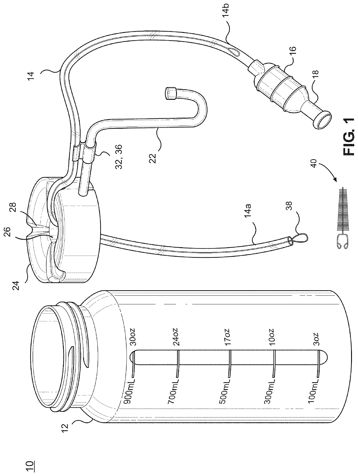
[0046]The term “proximal” and “proximate” as used herein refers to a position which is nearest to the patient receiving hydration through the mouthpiece. The mouthpiece is proximate to the supply tube, which is proximate to the reservoir since fluid travels from the re...


PUM


Abstract

An oral hydration system, which includes a fluid reservoir; a supply tube fluidly coupled to the reservoir at its distal end; and a mouthpiece pump molded as a single piece utilizing one pliable material and deformable along its entire length, wherein the mouthpiece pump is fluidly coupled at its distal end to a proximal end of the supply tube, wherein the mouthpiece pump or the supply tube comprises a one-way distal valve and the mouthpiece pump is sealed proximally with a proximal face in a form of a mouthpiece containing a proximal valve that seals until the pump is deformed by a user for the purpose of creating a priming and pumping action to draw fluid from the reservoir, through the supply tube and out of the mouthpiece pump to the user.

Description

CROSS REFERENCE TO RELATED APPLICATIONS[0001]This is a continuation in part of U.S. patent application Ser. No. 15 / 575,662, which is a U.S. national phase entry under 35 U.S.C. § 371 of international application no. PCT / US2017 / 014466, filed Jan. 21, 2017, now expired, which claims benefit of priority to U.S. patent application No. 62 / 282,000 filed Jan. 22, 2016, now expired; the content of each is herein incorporated by reference in its entirety.TECHNICAL FIELD[0002]The invention relates generally to an oral hydration system and more specifically to an oral hydration system that incorporates a pumping mechanism that provides variable flow rates for hydration and can be reversibly mounted to a variety of structures.BACKGROUND OF THE INVENTION[0003]Hydration is essential for humans to survive and operate at optimal levels. For many reasons such as physical exertion, limited mobility and other health factors people can have a hard time staying adequately hydrated. In the healthcare set...

Claims


Application Information

Patent Timeline
Patent Type & Authority Applications(United States)
IPC IPC(8): B05B11/00B05B15/62A45F3/16
CPCB05B15/62B05B11/0091B05B11/0075A45F3/16B05B11/3032A61G7/0503A61M3/0262A61M3/0279A61M2210/0625A61M3/0266A61M2209/082A61M2209/10A61J15/0011A61M3/0245B05B11/1032
Inventor HADEN, JIM
Owner HADEN JIM
Why Eureka
Try Eureka