Projection optical apparatus and projector

Active Publication Date: 2020-12-24
SEIKO EPSON CORP
View PDF0 Cites 1 Cited by
  • Summary
  • Abstract
  • Description
  • Claims
  • Application Information

AI Technical Summary

Benefits of technology

[0007]An advantage of the present disclosure is to reinforce a frame that holds an optical path deflect

Problems solved by technology

In the projection optical apparatus, however, a lens disposed in a position closest to the magnifying side has a large weight, so that a large load acts on a portion where the lens barrel that holds the magnifying-side lens group is bonded to the frame that holds the optical path deflector, such as a mirror.
When the thickness of the frame

Method used


Image

  • Projection optical apparatus and projector
  • Projection optical apparatus and projector
  • Projection optical apparatus and projector

Examples


Embodiment Construction

Overall Configuration

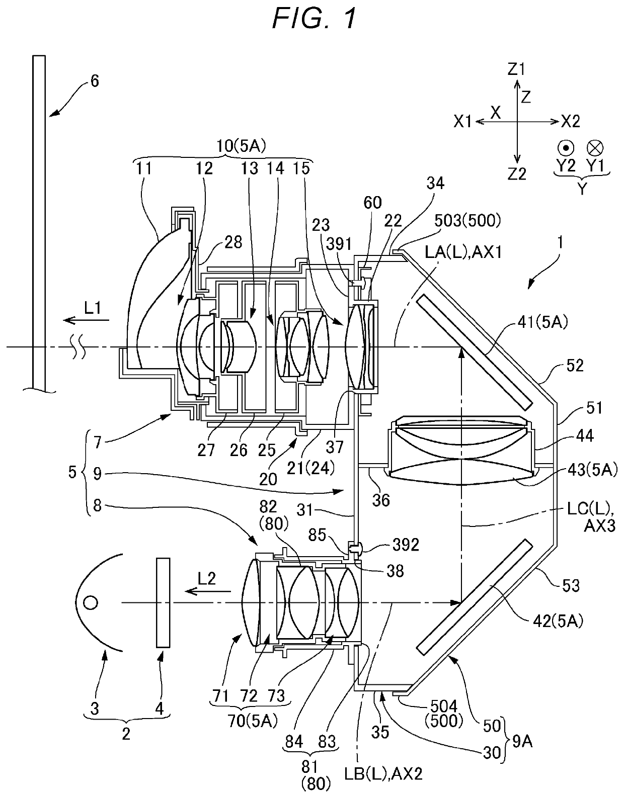
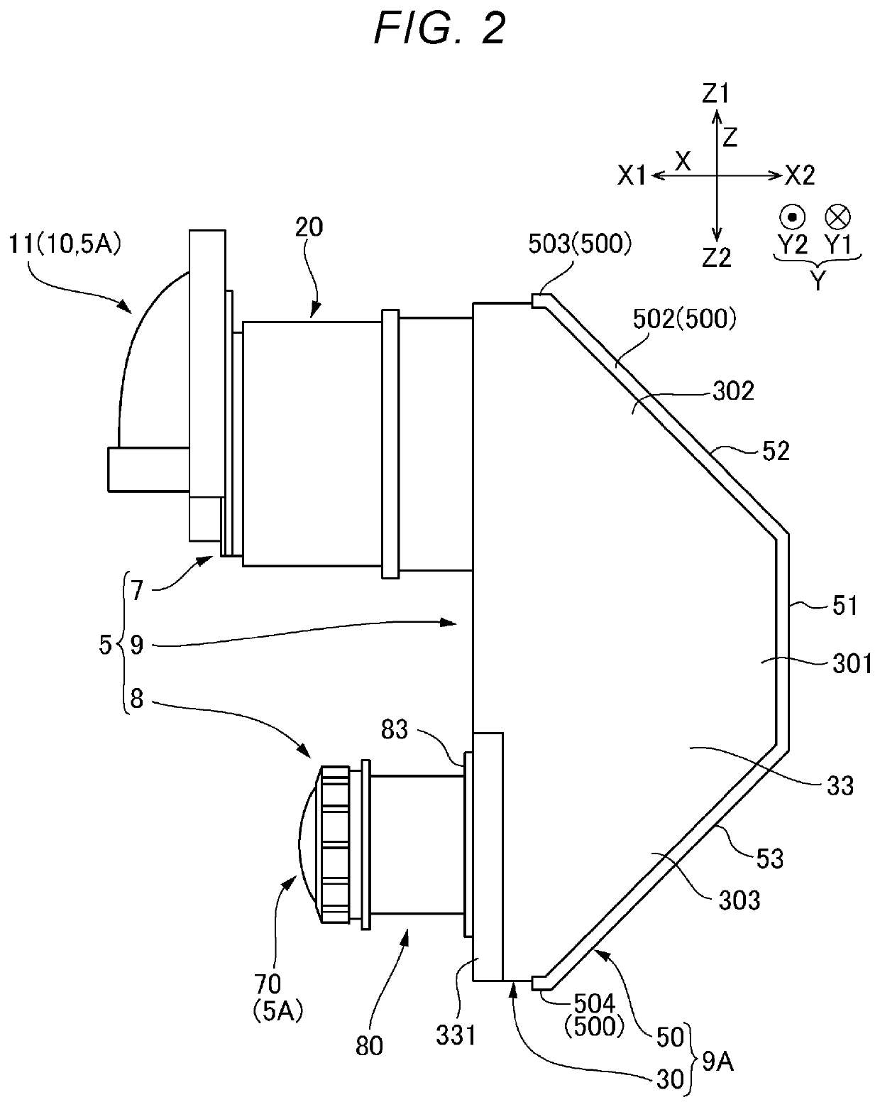
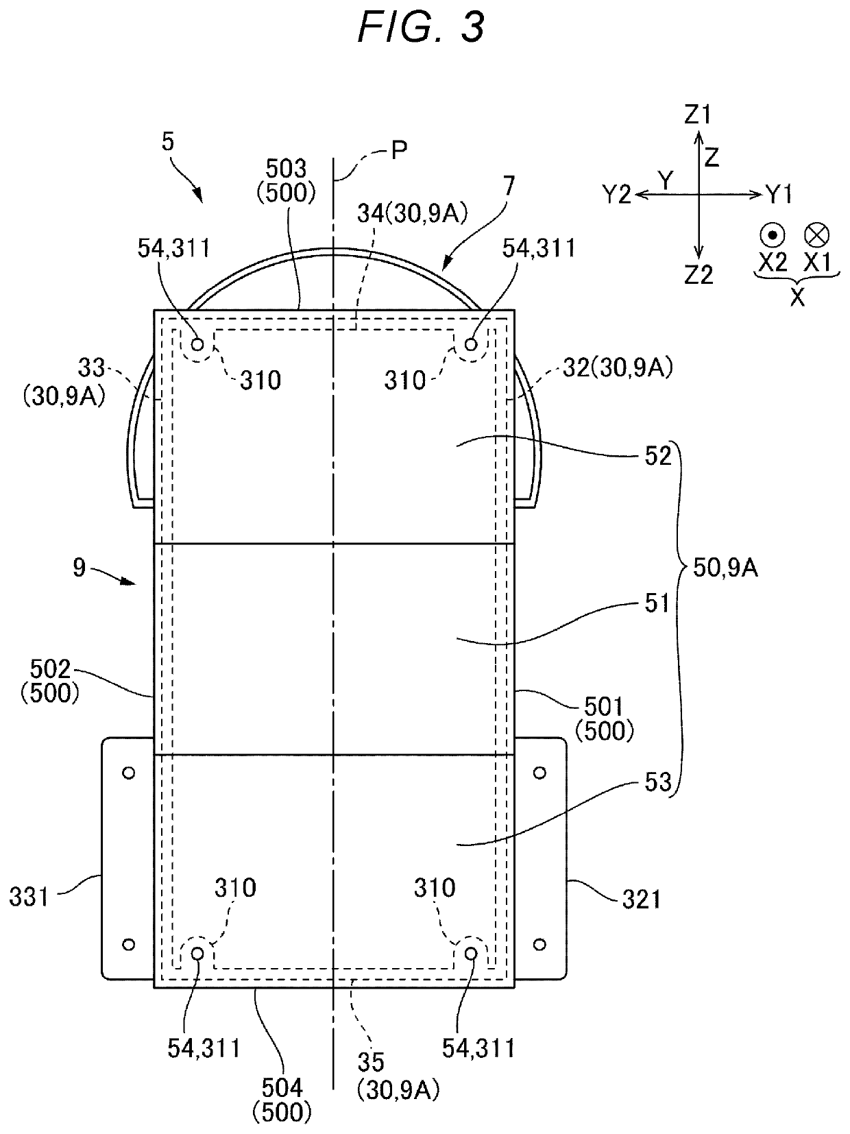
[0014]An exemplary embodiment of the present disclosure will be described below with reference to the drawings. FIG. 1 is a descriptive diagram showing an internal configuration of a projection optical apparatus 5 and a schematic configuration of a video light generator 2 in a projector 1 according to the present embodiment. FIG. 2 is a side view of the projection optical apparatus 5 according to the present embodiment. FIG. 3 is a rear view of the projection optical apparatus 5 in FIG. 2 viewed from the side facing a cover frame 50. FIG. 4 is a partial perspective view of a portion where a first lens barrel 20 and a frame main body 30 are bonded to each other with the portion viewed from a demagnifying side L2.

[0015]The projector 1 includes the video light generator 2 and the projection optical apparatus 5, as shown in FIG. 1. The video light generator 2 and the projection optical apparatus 5 are disposed in an exterior enclosure that is not shown. The exterior...


PUM


Abstract

A projection optical apparatus includes a first lens group including a first optical axis, a first optical path deflector, a second optical path deflector, a second lens group including a second optical axis, a first lens barrel, a second lens barrel and a frame. The frame includes a frame main body and a cover frame. The frame main body includes a lens barrel attachment part including first and second openings, and first and second side parts facing each other and extending in a direction along a plane containing the first optical axis and a third optical axis between the first optical path deflector and the second optical path deflector. The cover frame is disposed at an opposite side to a lens barrel attachment part side with respect to the first and second optical path deflectors, and includes an outer circumferential part fixed to the the first and second side parts.

Description

[0001]The present application is based on, and claims priority from JP Application Serial Number 2019-116211, filed Jun. 24, 2019, the disclosure of which is hereby incorporated by reference herein in its entirety.BACKGROUND1. Technical Field[0002]The present disclosure relates to a projection optical apparatus and a projector that projects video light by using the projection optical apparatus.2. Related Art[0003]There has been a projector that enlarges video light produced by using light from a light source and projects the video light on a screen via a projection system.[0004]JP-A-2016-156986 discloses a projector of this type (projection-type display apparatus). The projection-type display apparatus disclosed in JP-A-2016-156986 deflects the optical path by using an optical path deflector, such as a mirror, when projecting the video light produced by a light modulator (light valve) in accordance with image information on the screen.[0005]In the projection optical apparatus, in wh...

Claims


Application Information

Patent Timeline
IPC IPC(8): H04N9/31G03B21/20
CPCG03B21/2066H04N9/3152G03B21/005G03B21/145G03B21/28H04N9/3102
Inventor OKUBO, HIROFUMI
Owner SEIKO EPSON CORP
Why Eureka
Try Eureka