Head mounted display
- Summary
- Abstract
- Description
- Claims
- Application Information
AI Technical Summary
Benefits of technology
Problems solved by technology
Method used
Image
Examples
example 1
2. Example 1
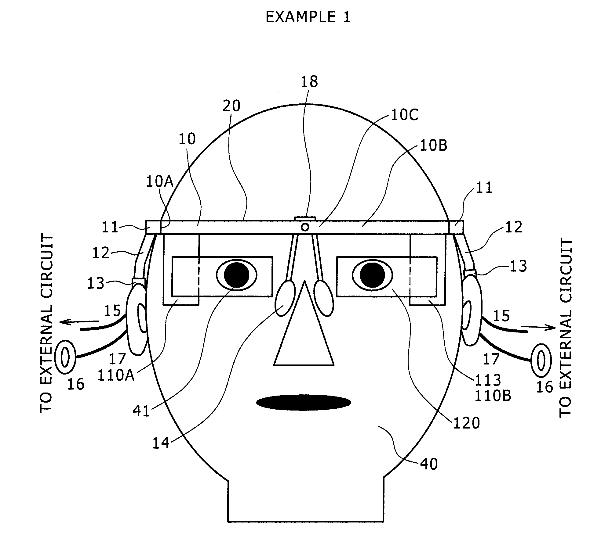
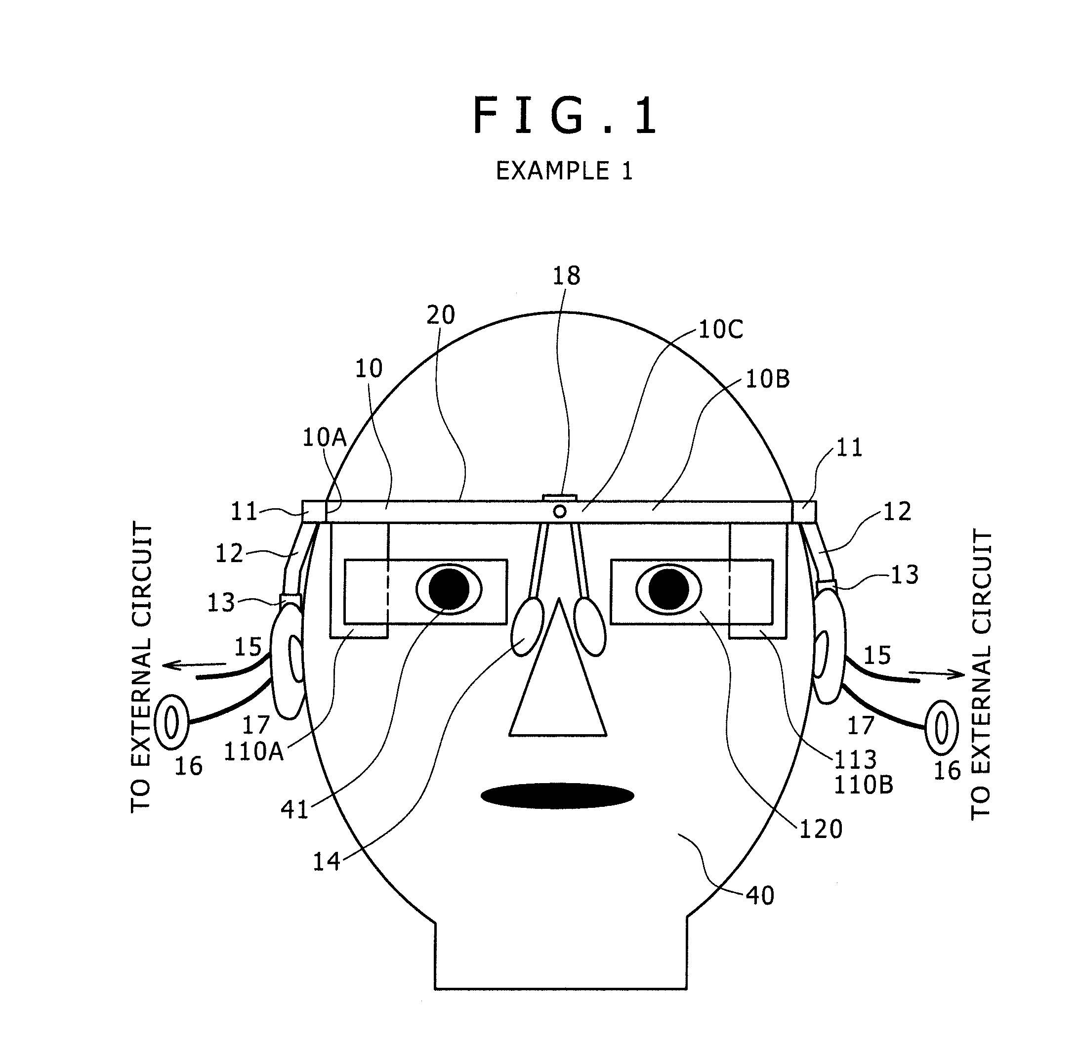
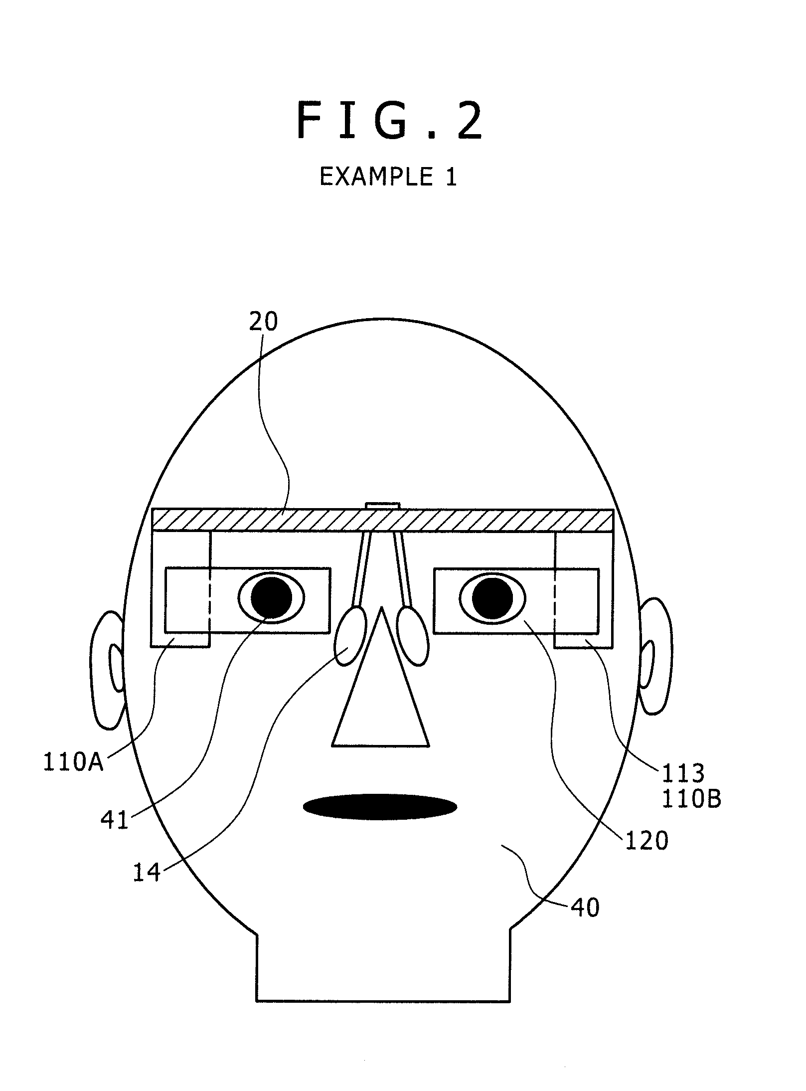
[0130]Example 1 relates to a head mounted display according to an embodiment of the present invention. FIG. 1 shows a schematic view of the head mounted display of Example 1, as viewed from the front side, and FIG. 2 shows a schematic view of the head mounted display of Example 1 (in an assumed condition where a frame is removed), as viewed from the front side. In addition, FIG. 3 shows a schematic view of the head mounted display of Example 1, as viewed from the upper side, and FIG. 4 shows the condition where the head mounted display of Example 1 is mounted to the head of an observer 40, as viewed from the upper side. Incidentally, in FIG. 4, only the image display devices are shown and the frame is omitted, for convenience. Besides, FIG. 5 shows a perspective view of the head mounted display of Example 1, as viewed from a front upper side, and FIG. 6 shows a perspective view of the same as viewed from a rear lower side. Further, FIG. 7 shows an exploded view of compon...
example 2
3. Example 2
[0157]Example 2 resides in a modification of Example 1. FIG. 9 shows a conceptual diagram of an image display device 200 in a head mounted display according to Example 2. As shown in FIG. 9, in Example 2, an image generating device 210 includes an image generating device of the second configuration. Specifically, the image generating device includes:
[0158](a) a light source 251;
[0159](b) a collimating optical system 252 by which beams emitted from the light source 251 are made to be parallel beams;
[0160](c) a scanning section 253 configured to scan the parallel beams emitted from the collimating optical system 252; and
[0161](d) a relay optical system 254 by which the parallel beams scanned by the scanning section 253 are relayed and emitted. Incidentally, the image generating device 210 as a whole is accommodated in a casing 213 (in FIG. 9, indicated by dot-dash lines). The casing 213 is provided with an aperture (not shown), and the beams are emitted from the relay opti...
example 3
4. Example 3
[0164]Example 3 also resides in a modification of Example 1. FIG. 10A shows a conceptual diagram of an image display device 300 in a head mounted display according to Example 3. Besides, FIG. 10B shows a schematic sectional view illustrating part of a reflection-type volume holographic diffraction grating, in an enlarged form. In Example 3, an image generating device 110 includes an image generating device of the first configuration, in the same manner as in Example 1. In addition, an optical device 320 is the same as the optical device 120 of Example 1 in basic configuration or structure, as it includes:
[0165](a) a light guide plate 321 which as a whole is disposed on the side of the center of the face of the observer 40 relative to the image generating device 110, on which the beams emitted from the image generating device 110 are incident, through which the beams are guided, and from which the beams are emitted toward the pupil 41 of the observer 40;
[0166](b) a first ...
PUM
 Abstract
Description
Claims
Application Information
 - R&D
- Intellectual Property
- Life Sciences
- Materials
- Tech Scout
- Unparalleled Data Quality
- Higher Quality Content
- 60% Fewer Hallucinations
Browse by: Latest US Patents, China's latest patents, Technical Efficacy Thesaurus, Application Domain, Technology Topic, Popular Technical Reports.
© 2025 PatSnap. All rights reserved.Legal|Privacy policy|Modern Slavery Act Transparency Statement|Sitemap|About US| Contact US: help@patsnap.com


