Milker unit short milk tube with milk claw end connector

Active Publication Date: 2021-02-25
GEA FARM TECH
View PDF0 Cites 1 Cited by
  • Summary
  • Abstract
  • Description
  • Claims
  • Application Information

AI Technical Summary

Benefits of technology

[0009]The short milk tube may also include a flexible portion for reliable bending to seal the short milk tube, and a reinforced portion to improve durability. Controlled and reliable short milk tube flexing can be provided by a grooved portion on the short milk tube positioned to conform to a beveled portion of a milking claw inlet, thereby maximizing air flow reduction when not in use and also during the process of attaching the milker unit to the cow. The grooved portion is prone to excessive liner wear, so a reinforced portion slightly upstream from the grooved portion is also provided to engage an end portion of the milk claw inlet. These critical features require relatively precise positioning of the short milk tube attachment to the milk claw inlet to function properly, so the position and release device is used for installing the milk tube consistently and accurately.
[0010]A reliable position and release device on the end of the short milk tube in accordance with the present invention ensures that the flexing and reinforced portions are located accurately relative to the end of the milking claw inlet. Incompletely

Problems solved by technology

Incompletely positioning the short milk tube on the pointed end of the milk claw inlet could cause the flexing portion not to align properly and re

Method used


Image

  • Milker unit short milk tube with milk claw end connector
  • Milker unit short milk tube with milk claw end connector
  • Milker unit short milk tube with milk claw end connector

Examples


Embodiment Construction

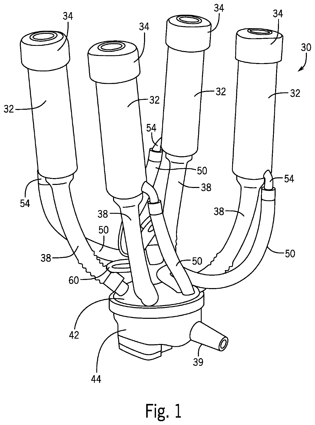
[0024]Illustrated generally in FIG. 1 is a traditional milker unit 30 having a teat cup 32, a teat cup liner 34 disposed in the teat cup 32, a short milk tube 38 joined to or formed integrally with the teat cup liner 34, a milking claw 42, and milk bowl 44 at its downstream end. There is one teat cup 32, liner 34, and short milk tube 38 for each teat of the dairy animal. The milking claw 42 and milk bowl 44 collect milk from all short milk tubes 38. (The milker unit illustrated in FIG. 1 is depicted for background and does not illustrate the short milk tube invention described below.) The objective of the milker unit 30 is to draw milk away from the dairy animal teats, out of a milk bowl outlet 39, and into the central dairy milk lines (not illustrated), reduce the amount of milk flowing back toward the teat, and reduce the amount of air drawn into the central dairy milk line when vacuum is being applied.

[0025]During milking, a dairy animal teat is inserted through an upper orifice ...


PUM


Abstract

A milker unit short milk tube having a downstream milk claw connection end; a position and release device joined to and extending away from the downstream milk claw connection end; a controlled flexible portion disposed in an upstream direction from the position and release device; a reinforced portion disposed in upstream direction from the controlled flexible portion; and an interior milking claw inlet sealing surface.

Description

FIELD AND BACKGROUND OF THE INVENTION[0001]The present invention relates generally to dairy milker unit short milk tubes, and more particularly to short milk tubes extending between an upstream milking teat cup liner and a downstream milk collection bowl and claw arrangement, and the connection to the claw inlet.[0002]In milk harvesting facilities, dairy animals are arranged in stalls and milker units are attached to the animals' teats to harvest milk. The milker units include a teat cup for each teat, a teat cup liner disposed inside each teat cup, a short milk tube joined to or formed integrally with each teat cup liner, and a milking claw and bowl assembly for collecting milk from all of the short milk tubes in the milker unit for passage to a central dairy milk pipeline.[0003]The dairy environment is harsh and milker units are subject to constant use, abuse from handling by dairy operators, and impacts from animals. Consequently, dairy milker unit components must be robust and s...

Claims


Application Information

Patent Timeline
IPC IPC(8): A01J5/04
CPCA01J5/044
Inventor HEDLUND, NATHAN
Owner GEA FARM TECH
Why Eureka
Try Eureka