

Two jaw adjustable and extendable wrench
a wrench and extension technology, applied in the field of wrenches, can solve the problems of reducing the range of wrenches that can be operated on, the distance between the fixed and the movable jaws is limited, etc., and achieve the effect of gracing the hex shape fasteners more efficiently
- Summary
- Abstract
- Description
- Claims
- Application Information
AI Technical Summary
Benefits of technology
Problems solved by technology
Method used
Image

Examples
Embodiment Construction
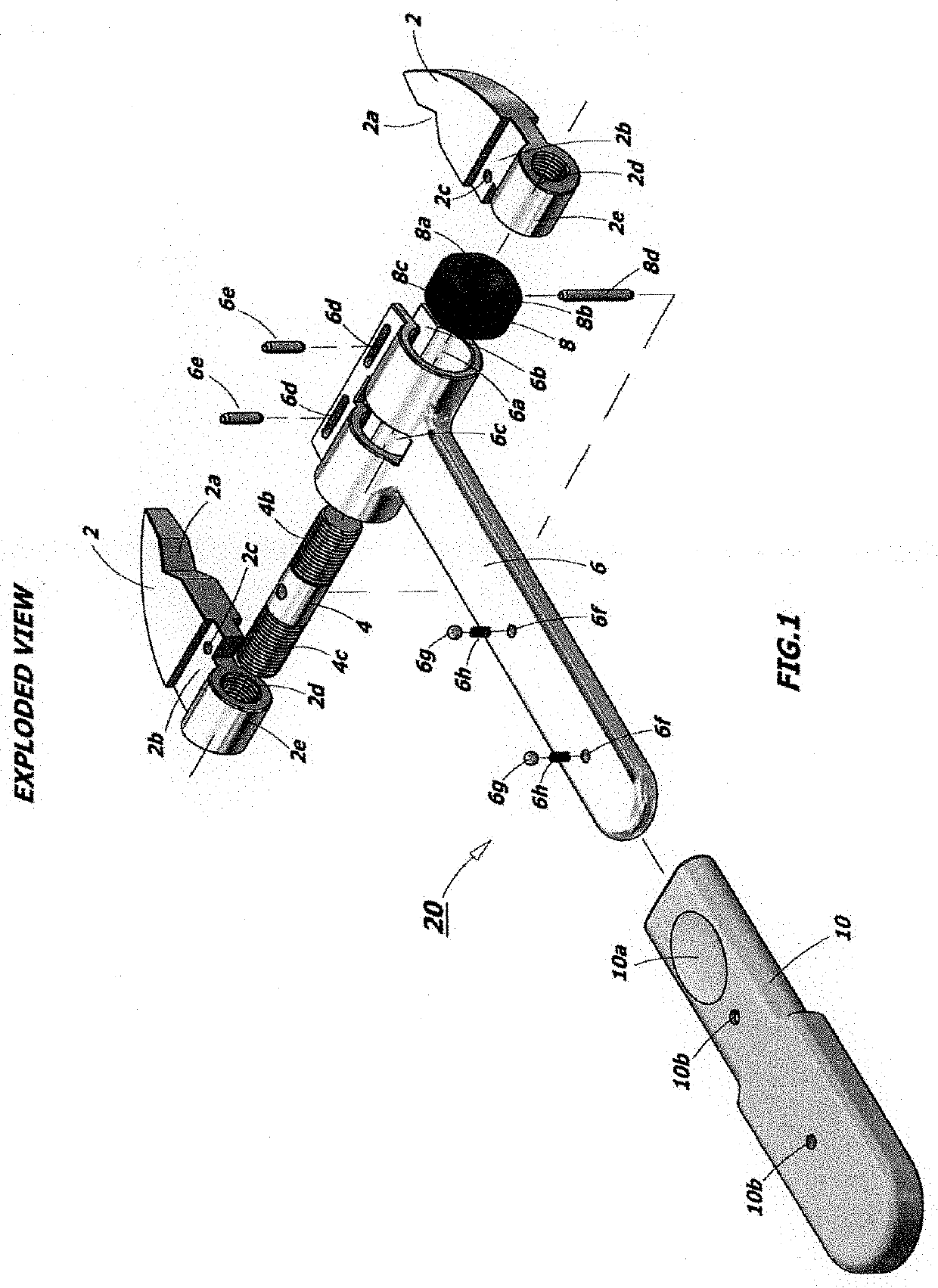
[0025]Referring to FIG. 1, jaws 2 of the wrench of the present invention is illustrated. V-notches 2a, angled at 120 degrees, are formed on the interior of both opposing jaws 2. The jaw necks 2b slides within the interior slotted horizontal channel 6b of T-frame, or yoke, 6. Vertical holes 2c retain two horizontal strap pins 6c that control the expansion and retraction of jaws 2 within right and left hand slots 6, the slots limiting movement of the jaws 2. Central knurled wheel 8a is rotateable to adjust jaws 2 to ride inward or outward when wheel 8 is rotated in the clockwise or counterclockwise direction. The jaws 2 ride horizontally within slot 6d of the upper horizontal T-frame 6. Exterior member 2e rides within horizontal bore 6c of T-frame 6. The right hand thread 2d and left hand thread 2e of jaws 2 are connected to horizontal right and left hand thread adjusting screw 4. The right hand external thread for 4b mates with thread 2d, thread 4c mateing with opposing jaw 2c via th...
PUM
 Abstract
Description
Claims
Application Information