Biometric system and method

a biometric system and biometric technology, applied in the field of biometric technique, can solve the problems of difficulty in verbally understanding the balance of a cane and a walking foot pressure direction, and achieve the effect of efficient grasping the walk state and the posture state, reducing the burden on the staff, and shortening the tim

Active Publication Date: 2021-04-29
HIROSHIMA UNIVERSITY +1
View PDF16 Cites 0 Cited by
  • Summary
  • Abstract
  • Description
  • Claims
  • Application Information

AI Technical Summary

Benefits of technology

[0008]According to the present invention, it is possible to more efficiently grasp the walk state and the posture state. Reduction in the burden on the staff has an effect of allowing the staff to give explanations and instructions in a shorter time.

Problems solved by technology

The technique described in JP 2012-176170 A can display the balance of foot pressure and the body position as to which part of the foot the pressure is applied, but the technique has had a problem of difficulty in understanding the direction in which the foot pressure is applied during walking.
In addition, a cane is used for walk training, but it has been difficult to verbally understand how to balance with a device such as a cane.

Method used


Image

  • Biometric system and method
  • Biometric system and method
  • Biometric system and method

Examples


embodiments

[0026]Embodiments of the present invention will be described below with reference to the drawings. Each embodiment is an example for explaining the present invention, and is omitted or simplified as appropriate for a clearer description. The present invention can also be carried out in various other forms. Unless otherwise specified, each component may be singular or plural.

[0027]The position, size, shape, range, and the like of each component presented in the drawings do not necessarily represent the actual position, size, shape, range, and the like, for the purpose of facilitating understanding of the invention. Therefore, the present invention is not necessarily limited to the positions, sizes, shapes, ranges, and the like disclosed in the drawings.

[0028]As an example of various types of information, the database may include “table”, “list”, and “queue”, and various types of information may be expressed by other data structures. For example, various types of information such as “...

first embodiment

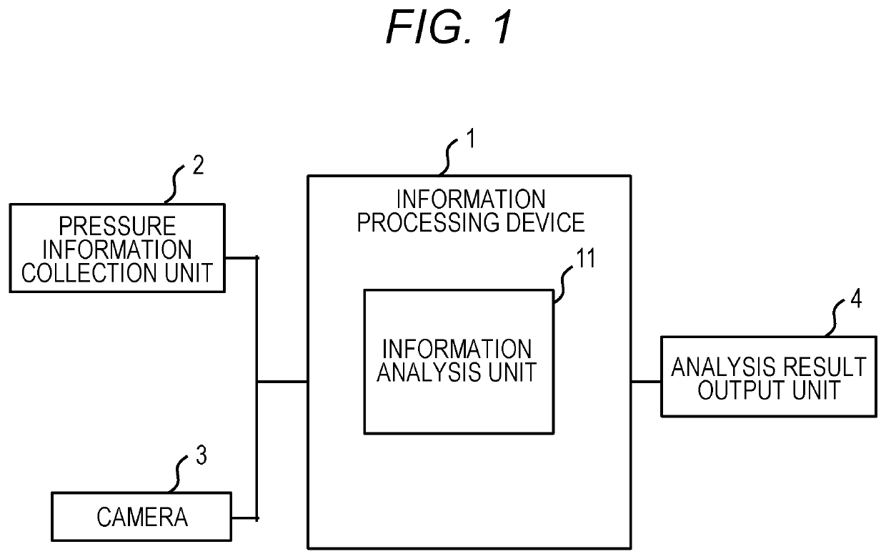
[0032]FIG. 1 is an overall configuration diagram of a biometric system used for walk support according to the embodiment.

[0033]An information processing device 1 receives information on pressure from a pressure information collection unit 2 and receives image information of a subject from a camera 3. An information analysis unit 11 obtains a floor reaction force vector of the subject on the basis of information on pressure to be input from the pressure information collection unit 2. Instead of the floor reaction force vector, a pressure barycenter position may be obtained. Furthermore, the information analysis unit 11 receives an image of the subject acquired by the camera 3 and detects the skeleton of the subject from the image of the subject. The information analysis unit 11 synchronizes the information of the floor reaction force vector obtained from the information on the pressure received from the pressure information collection unit 2 with the information of the skeleton of th...

second embodiment

[0075]FIG. 11 is a view illustrating a display example of the skeleton and the pressure value when a cane according to the second embodiment is used. In the first embodiment, the subject 10 performs walk training without a cane, while in the second embodiment, as shown in the left side of FIG. 11, the subject 10 performs walk training with a cane 121.

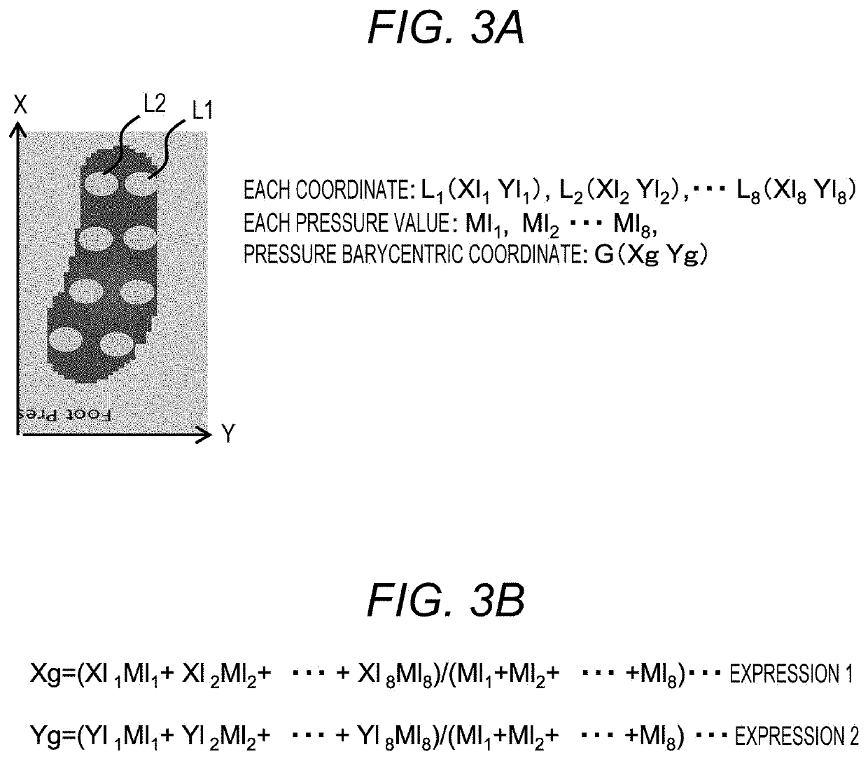
[0076]In the second embodiment, the pressure information collection unit 2 of FIG. 1 includes, in addition to the pressure sensor unit of the sole illustrated in FIG. 3A, a hand pressure sensor 122 that supports the cane 121, and a cane pressure sensor 123 at a position where the cane touches the ground. This embodiment is similar to the first embodiment except that the hand pressure sensor 122 and the cane pressure sensor 123 are added to process information on the pressure by the added sensors.

[0077]The pressure distribution detected by each pressure sensor is output to the analysis result output unit 4 by the information analysis uni...


PUM


Abstract

A biometric system includes: a camera that captures a subject; a pressure information collection unit that detects a pressure value of at least one sole of the subject; a skeleton direction vector calculation unit that calculates a skeleton direction vector of the subject captured by the camera; a floor reaction force vector calculation unit that calculates a floor reaction force vector on a basis of information on pressure from the pressure information collection unit; and an analysis result output unit that displays, in a superimposing manner, the skeleton direction vector calculated by the skeleton direction vector calculation unit and the floor reaction force vector calculated by the floor reaction force vector calculation unit.

Description

BACKGROUND OF THE INVENTION1. Field of the Invention[0001]The present invention relates to a biometric technique that supports walk training.2. Description of the Related Art[0002]At medical and nursing care facilities, therapists and caregivers observe conditions of patients during walk training, and give instructions on how to balance. However, since verbal instructions are difficult to understand, it is necessary to have a system that visualizes the situation of balance and presents the walk situation in an easily recognizable manner.[0003]JP 2012-176170 A discloses a technique that realizes health maintenance and care including foot-part balance correction and fall prevention. JP 2012-176170 A discloses a technique that provides functional and effective training necessary for balance correction by evaluating the function of a hallux, the function of a thenar part, and the function of a hypothenar part, which are important for balance correction, from the pressure variations from...

Claims


Application Information

Patent Timeline
Patent Type & Authority Applications(United States)
IPC IPC(8): A61B5/11A61B5/00A61H3/02
CPCA61B5/1128A61B5/0077A61H2201/5071A61H3/02A61B5/742A61B5/1038A61H1/00A61H2203/0406A61H2230/62A61B5/112
Inventor NISHIMURA, AYAKOATSUMORI, HIROKAZUFUNANE, TSUKASAKANDORI, AKIHIKONAKAMURA, YASUAKIOBATA, AKIKOKOMATSU, YUTOHAMA, SEIJITSUJI, TOSHIO
Owner HIROSHIMA UNIVERSITY
Why Eureka
Try Eureka