Automatic lubricator for lubricating an object

a technology of automatic lubrication and lubrication device, which is applied in the direction of lubrication elements, mechanical apparatus, signal processing, etc., can solve the problems of preventing the dispensing of lubricant, and achieve the effect of improving functionality, quickly, efficiently and/or accurately determining one or more lubrication parameters

Active Publication Date: 2021-04-08
DODGE INDS +1
View PDF0 Cites 1 Cited by
  • Summary
  • Abstract
  • Description
  • Claims
  • Application Information

AI Technical Summary

Benefits of technology

[0004]According to the present disclosure, there is provided an improved lubricator that provides improved and / or enhanced functionality, e.g. in terms of reliably, quickly, efficiently and / or accurately determining one or more lubrication parameters.

Problems solved by technology

Depending on a condition or state of the lubricant container, such as e.g. a blockage of the output, however, dispensing of lubricant may be blocked, although the electric motor is actuated and / or powered.

Method used


Image

  • Automatic lubricator for lubricating an object
  • Automatic lubricator for lubricating an object
  • Automatic lubricator for lubricating an object

Examples


Embodiment Construction

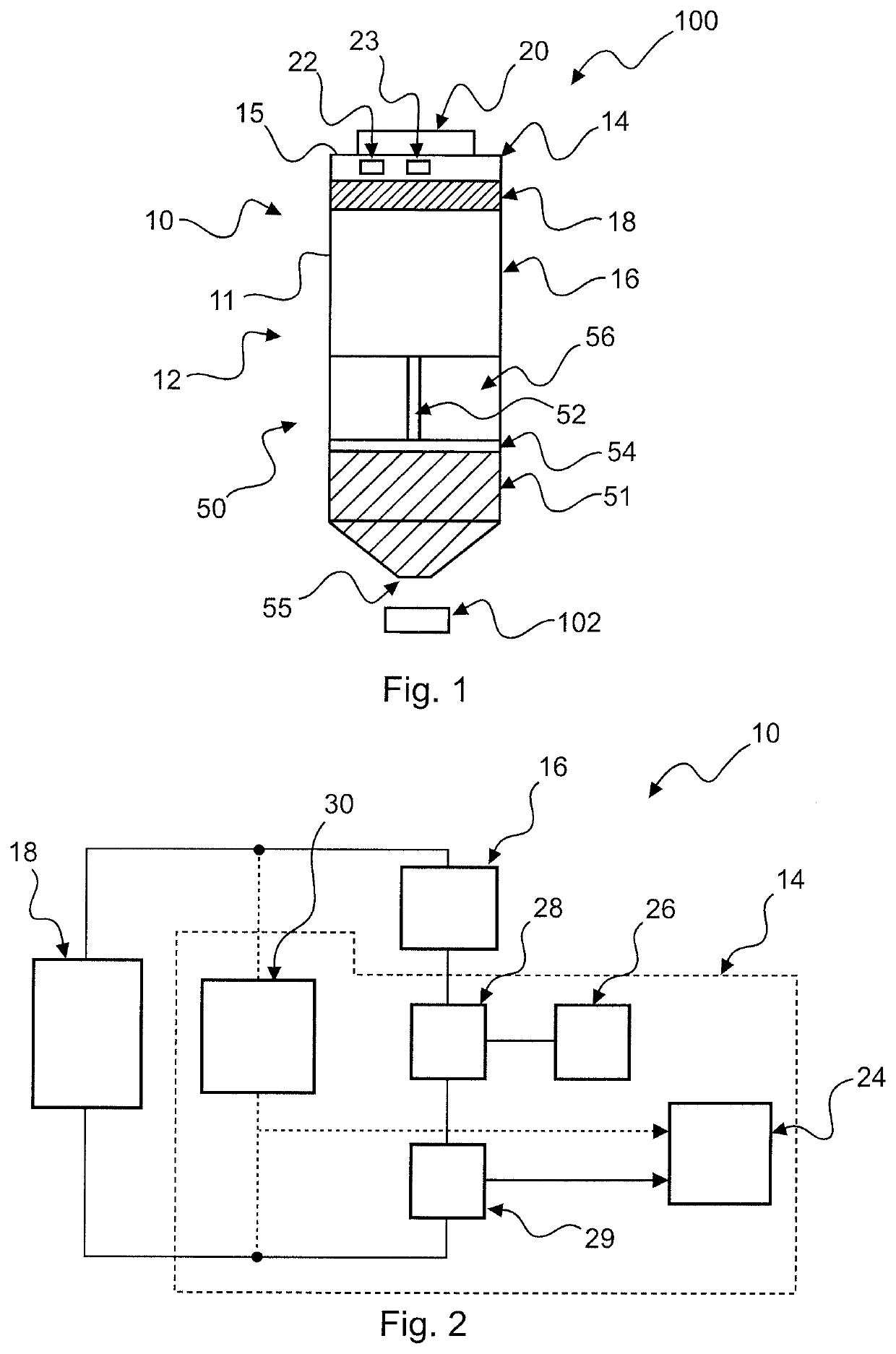
[0086]FIG. 1 shows a cross-sectional view of a lubrication system 100 according to an exemplary embodiment. FIG. 2 shows a block diagram of a part of a lubricator 10 of the lubrication system 100 of FIG. 1.

[0087]The lubrication system 100 comprises a lubricator 10 with a housing 11 having a coupling section 12 which is coupled to a lubricant container 50 of the lubrication system 100. The container 50 can be detachably attached to the lubricator 10 and / or the housing 11 by any suitable connection, such as e.g. a threaded coupling and / or threaded connection.

[0088]The lubricant container 50 comprises a rotatable shaft 52 and / or rotatable screw 52, on which a piston 54 is displaceably arranged, mounted and / or attached. Further, the container 50 contains a lubricant 51 which is to be dispensed via an outlet 55 and / or output 55 of the container 50 during a lubrication action. Upon rotation of the rotatable shaft 52, the piston 54 is displaced in a direction towards the output 55, such th...


PUM


Abstract

An automatic lubricator for lubricating an object is described, which comprises a housing with a coupling section configured to couple with a lubricant container containing a lubricant, wherein the lubricant container comprises a rotatable shaft with a piston to dispense the lubricant from an output of the lubricant container. The lubricator further comprises an electric motor configured to drive the rotatable shaft of the lubricant container during at least one lubrication action, such that at least a part of the lubricant is dispensable from the lubricant container during the at least one lubrication action, and a power supply configured to supply the electric motor with a supply current during the at least one lubrication action. The lubricator further comprises a control circuitry configured to acquire a current signal indicative of the supply current over time during at least a part of the at least one lubrication action, determine a periodicity of the acquired current signal, and determine, based on the determined periodicity, at least one lubrication parameter indicative of the at least one lubrication action.

Description

TECHNICAL FIELD[0001]The present invention relates to an automatic lubricator and / or lubrication device for lubricating an object. The invention further relates to a lubrication system comprising such lubricator, a method of lubricating an object, a computer program, and a non-transitory computer-readable medium storing such computer program.TECHNICAL BACKGROUND[0002]Automatic lubricators, lubrication devices and / or lubrication systems are usually used for ensuring a smooth and reliable operation of an apparatus, engine, device and / or industrial system by lubricating one or more objects, parts, portions and / or members thereof. Such objects, parts, portions and / or members can, for example, be and / or comprise a bearing, a shaft or the like.[0003]Generally, an automatic lubricator can automatically apply lubricant onto and / or into the object that should be lubricated at a specified lubrication time, with a certain lubrication frequency and / or in certain lubrication time intervals. This...

Claims


Application Information

Patent Timeline
Patent Type & Authority Applications(United States)
IPC IPC(8): F16N7/00F16N29/04F16N29/02
CPCF16N7/00F16N29/04F16N2270/70F16N2230/02F16N2230/10F16N29/02
Inventor WAWRZOLA, GRZEGORZLEWANDOWSKI, DANIELLAMBERT, ERICHEWITT, GREGRDZANEK, ARTUR
Owner DODGE INDS
Why Eureka
Try Eureka