Automatic lubricator for lubricating an object

a technology of automatic lubrication and lubrication device, which is applied in the direction of lubrication elements, mechanical apparatus, engine pressure, etc., can solve the problems of shortening the life of the object and/or the system or apparatus comprising the object, affecting the operation of the object, and the cost of the sensor being not connected and/or associated with the container, so as to improve the effect of functionality and/or enhanced the

Active Publication Date: 2021-07-01
DODGE ACQUISITION CO +1
View PDF0 Cites 3 Cited by
  • Summary
  • Abstract
  • Description
  • Claims
  • Application Information

AI Technical Summary

Benefits of technology

[0004]According to the present disclosure, there is provided an improved lubricator, e.g. that provides improved and / or enhanced functionality.

Problems solved by technology

Such abnormal working condition, is for example a lubricant container output blockage, which may prevent proper dispensing of the lubricant from the container and could lead to insufficient lubrication of the object.
In turn, this could shorten a lifetime of the object and / or the system or apparatus comprising the object.
In turn, costs of the sensor may not be connected and / or associated with the container.

Method used


Image

  • Automatic lubricator for lubricating an object
  • Automatic lubricator for lubricating an object

Examples


Embodiment Construction

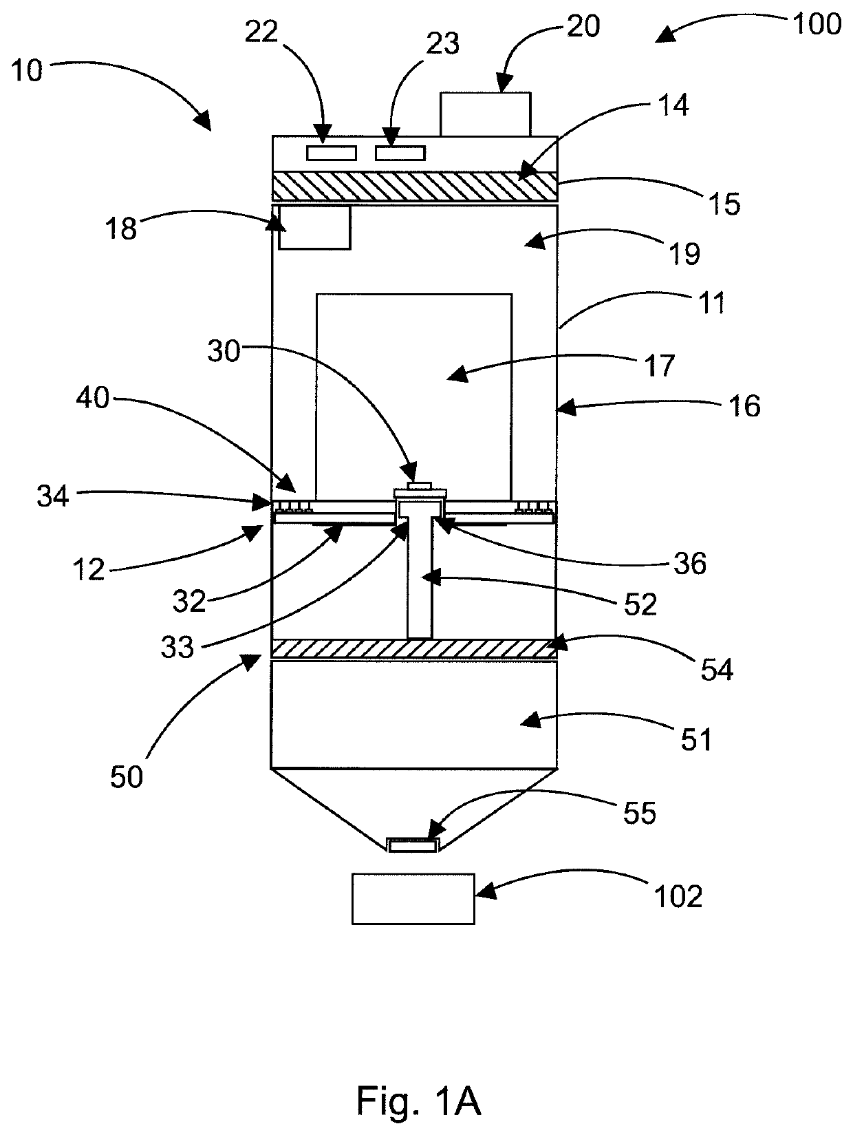
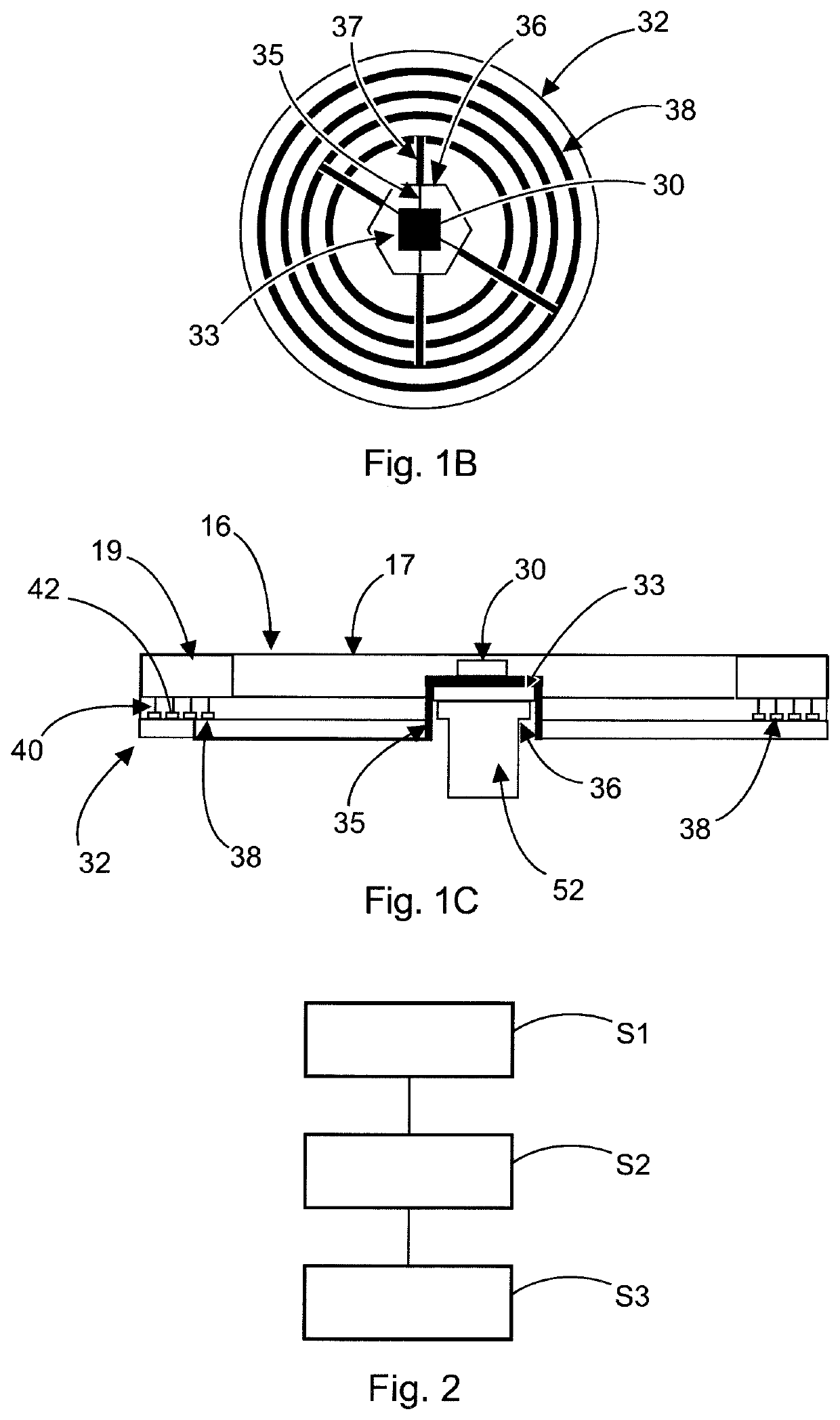
[0051]FIG. 1A shows a cross-sectional view of a lubrication system 100 according to an exemplary embodiment. FIG. 1B shows a top view of a sensor 30 and a rotatable circuit board 32 of the lubrication system 100 of FIG. 1A. FIG. 10 shows a cross-sectional view of the sensor 30 and the rotatable circuit board 32 of FIG. 1B.

[0052]The lubrication system 100 comprises a lubricator 10 with a housing 11 having a coupling section 12 which is coupled to a lubricant container 50 of the lubrication system 100. The container 50 can be detachably attached to the lubricator 10 and / or the housing 11 by any suitable connection, such as e.g. a threaded coupling and / or threaded connection.

[0053]The lubricant container 50 comprises a rotatable shaft 52 and / or rotatable screw 52, on which a piston 54 is displaceably arranged, mounted and / or attached. Further, the container 50 contains a lubricant 51 which is to be dispensed via an outlet 55 and / or output 55 of the container 50, e.g. during a lubricati...


PUM


Abstract

An automatic lubricator for lubricating an object is provided. The lubricator includes a housing with a coupling section configured to couple with a lubricant container containing a lubricant, wherein the lubricant container comprises a rotatable shaft with a piston to dispense the lubricant from an output of the lubricant container. The lubricator further comprises an electric motor configured to drive the rotatable shaft of the lubricant container, such that at least a part of the lubricant is dispensable from the lubricant container, at least one sensor configured to provide a sensor signal indicative of at least one of a force exerted by the electric motor onto the rotatable shaft and a force exerted by the lubricant onto the container, and a control circuitry configured to determine a blockage of the output of the lubricant container based on the sensor signal of the at least one sensor.

Description

TECHNICAL FIELD[0001]The present invention relates to an automatic lubricator and / or lubrication device for lubricating an object. The invention further relates to a lubrication system comprising such lubricator, a method of operating such lubricator, a computer program, and a non-transitory computer-readable medium storing such computer program.TECHNICAL BACKGROUND[0002]Automatic lubricators, lubrication devices and / or lubrication systems are usually used for ensuring a smooth and reliable operation of an apparatus, engine, device and / or industrial system by lubricating one or more objects, parts, portions and / or members thereof. Such objects, parts, portions and / or members can, for example, be and / or comprise a bearing, a shaft or the like.[0003]Generally, an automatic lubricator can automatically apply lubricant onto and / or into the object that should be lubricated at a specified lubrication time, with a certain lubrication frequency and / or in certain lubrication time intervals. ...

Claims


Application Information

Patent Timeline
Patent Type & Authority Applications(United States)
IPC IPC(8): F16N7/14F16N29/04
CPCF16N7/14F16N2270/70F16N2250/06F16N29/04F16N11/08
Inventor WAWRZOLA, GRZEGORZLEWANDOWSKI, DANIELLAMBERT, ERICRYBA, PIOTRHEWITT, GREGRDZANEK, ARTUR
Owner DODGE ACQUISITION CO
Why Eureka
Try Eureka