Compact Torque Converter

a torque converter and compact technology, applied in the direction of machines/engines, manufacturing tools, manufacturing, etc., can solve the problems of increasing the diameter of the engine crank pulley, belt slippage, and insufficient hardware to properly align the components, so as to improve the functionality increase or decrease the rpm of the rotating machine, and increase power

Inactive Publication Date: 2013-08-08
LAFONTAINE CHARLES YVON
View PDF0 Cites 0 Cited by
  • Summary
  • Abstract
  • Description
  • Claims
  • Application Information

AI Technical Summary

Benefits of technology

The present invention is a small torque converter that can improve the performance of rotating machines without needing to modify them or their surroundings. The torque converter can increase or decrease the speed of the rotating machine or increase the power it receives. There are two types of torque converters: separate mechanical systems that are attached to the rotating machine, or ones that are integrated into the machine itself. The torque converter can be used to enhance the functionality of rotating machines in either way without affecting them negatively.

Problems solved by technology

That hardware alone may not be enough to align properly the components and that other structures such as locating collars and pins required to maintain rotating machine components in alignment.
Unfortunately, decreasing pulley diameter of the rotating machine introduces the possibility of belt slippage since both belt wrap and belt contact arc length are important factors in power transmission.
Increasing the diameter of the engine crank pulley is also problematic.
Further, in high-speed engine applications such as in racing cars, the elevated engine RPM (as high as 16,000 RPM) would be detrimental to certain components.
For example, certain water pumps have an upper RPM limit that if exceeded, could destroy the pump.
But, increasing pulley diameter of the rotating machine introduces stresses at the shaft and pulley due to the increased rotational inertia of the larger pulley that may prove unacceptable.
Another problem is that decreasing the diameter of the crank pulley can produce an imbalance in the pulley / crank system.
Modifying rotating machine RPM in automotive applications is problematic, but equally difficult is modifying components to increase the amount of power transmitted from the engine to rotating machines (or accessories).
This may not be possible due to the increased cost, the extra engineering required to assure proper operation, or the space required to accommodate increased belt width may not be available.
As mentioned above, this approach would present structural redesign issues in high speed applications but in low speed applications, such as large diesel engines those issues are not relevant.
Unfortunately, this approach results in a decrease in crank-toaccessory pulley ratio, which results in a decrease in the RPM of the accessory.
This is true of high output alternators as well as conventional alternators, so even though power transmission capability to the rotating machine is improved, the decrease in RPM may result in an unacceptable decrease in alternator output.
Unfortunately, finding space or surfaces to mount extra idler pulleys in engine compartments can be problematic.
Many wind turbines rotate at speeds that are not favorable for power generation.
This is not true for 50 kW and smaller wind turbines where space and weight are at a premium.
Another class of generators are micro turbines that produce significantly smaller amounts of power (1.5 kW or less) where elaborate structures and earth works are not possible resulting in little or no head (low static water pressure).
In these instances turbine speed is limited to the speed of the stream as it passes by the turbine.

Method used


Image

  • Compact Torque Converter
  • Compact Torque Converter
  • Compact Torque Converter

Examples


first embodiment

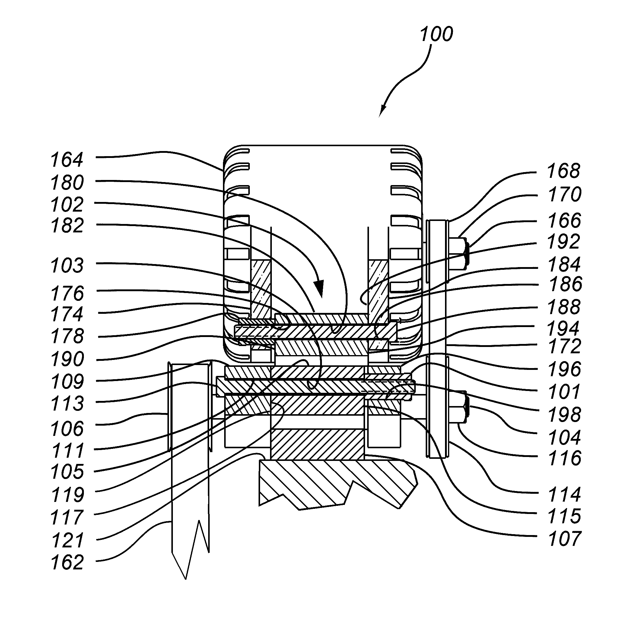
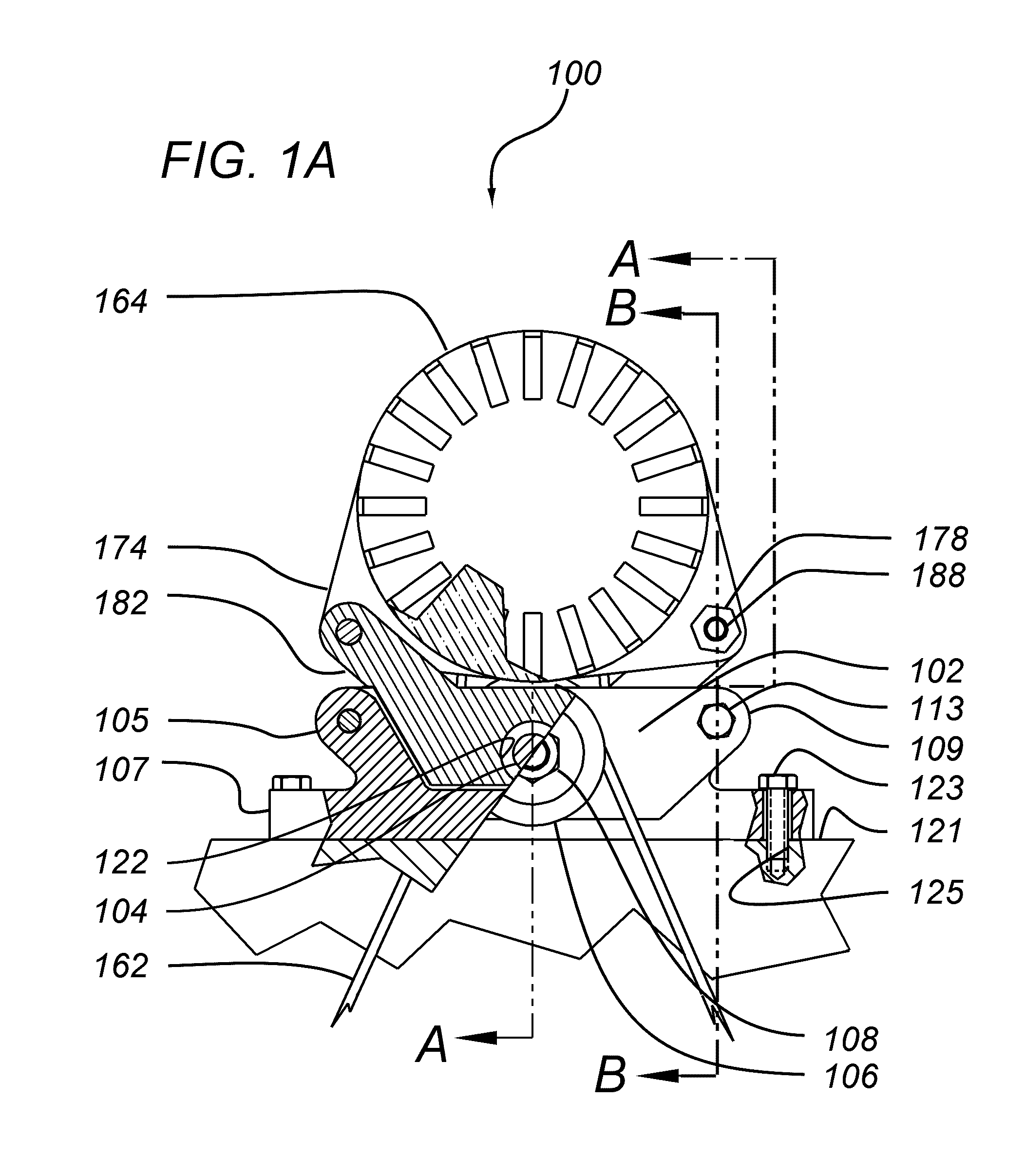
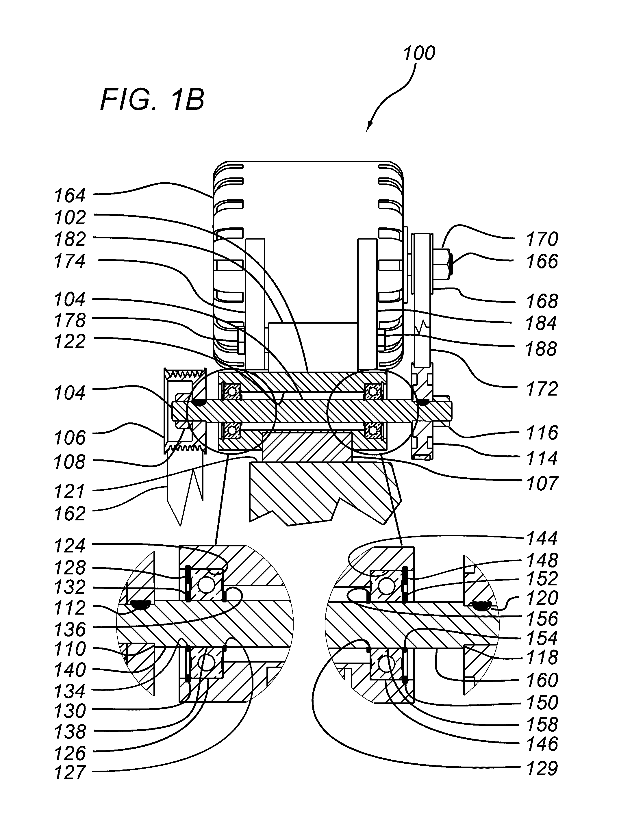
[0063]Referring now to FIGS. 1A-D, which are collectively referred to as FIGS. 1, a CTC assembly 100 comprises: a single shaft CTC body 102, a shaft 104 and a pulley 106. Pulley 106 is fixed to shaft 104 by nut 108 to press pulley 106 onto a shaft surface 110. Pulley 106 is also fixed to shaft 104 by a key 112. In certain applications the friction developed between pulley 106 and shaft surface 110 by nut 108 is sufficient to resist the torque developed by pulley 106 to eliminate the need for key 112. Press fitting or gluing pulley 106 onto shaft 104 can also be employed to fix pulley 106 adequately onto shaft 104.

[0064]CTC 102 body is preferably die-cast or sand-cast aluminum, such as type A356, but other suitable materials such as magnesium, steel, or engineered plastic such as polyamide-imide can be utilized. Alternatively, CTC 102 body can be machined from a solid billet of aluminum such as type 6061-T651 or other suitable material such as magnesium, steel, engineered plastic, or...

second embodiment

[0095]Referring now to FIGS. 3A-3E, which are collectively referred to as FIG. 3, a CTC assembly 300 comprises a twin shaft CTC body 302, a first shaft 304a, and pulley 306a, which is fixed to shaft 304a by nut 308a pressing pulley 306a onto shaft surface 310a. Pulley 306a is fixed to shaft 304a by key 312a. In certain applications the friction developed between pulley 306a and shaft surface 310a by nut 308a is sufficient to eliminate the need for key 312a. Press fitting or gluing pulley 306a onto shaft 304a can also be employed to fix pulley 306a adequately onto shaft 304a. Pulley 314a is maintained on shaft 304a by nut 316a compressing pulley 314a onto shaft surface 318a. Pulley 314a is fixed to shaft 304a by key 320a. In certain applications the friction developed between pulley 314a and shaft surface 318a by nut 316a is sufficient to eliminate the need for key 320a. Press fitting or gluing pulley 314a onto shaft 304a can also be employed to fix pulley 306a adequately onto shaft ...

third embodiment

[0110]Referring now to FIGS. 4A-4E, collectively referred to as FIG. 4, a CTC assembly 400 comprises CTC body 402, a shaft 404, and pulley 406 which is fixed to shaft 404 by nut 408 pressing pulley 406 onto shaft surface 410. Pulley 406 is fixed to shaft 404 by key 412. In certain applications, the friction developed between pulley 406 and shaft surface 410 by nut 408 is sufficient to resist the torque being developed eliminating the need for key 412. Press fitting or gluing pulley 406 onto shaft 404 can also be employed to fix pulley 406 adequately onto shaft 404. Pulley 414 is maintained on shaft 404 by nut 416 pressing pulley 414 onto shaft surface 418. Pulley 414 is also fixed to shaft 404 by key 420. In certain applications the friction developed between pulley 414 and shaft surface 418 by nut 416 is sufficient to eliminate the need for key 420. Press fitting or gluing pulley 414 onto shaft 404 can also be employed to fix pulley 406 adequately onto shaft 404.

[0111]CTC body 402 ...


PUM

PropertyMeasurementUnit
Fractionaaaaaaaaaa
Timeaaaaaaaaaa
Forceaaaaaaaaaa

Abstract

An assembly provides an indirect, rather than direct, drive from a power source to a rotating machine powered by the power source. The assembly includes one or more first pulleys that are connected to the drive source by one or more first belts, and one or more second pulleys that are connected to the rotating machine. Power is transmitted by the power source to the one or more first pulleys, to the one or more second pulleys by a shaft, and to the rotating machine by one or more second belts connecting the one or more second pulleys to a pulley of the rotating machine. The assembly provides for greater speed of and / or torque transmission to the rotating machine with fewer associated problems than if the rotating machine were connected directly to the power source.

Description

BACKGROUND OF THE INVENTION[0001]The present invention relates to the enhancement in output of rotating machines such as alternators, generators, propellers, and pumps typically driven by a power source such as electric motors, reciprocating engines, micro-hydro turbines, or other power sources that produce rotary output. Typically the rotating machine is linked to the power source through belts or chains via pulleys mounted onto both the motor output shaft and rotating machine input shaft. Improvements in rotating machine output would also be realized in systems where the power source (drive motor) output shaft is coupled directly (direct drive) to the input shaft of the present invention.[0002]The physical characteristics, geometries, and components of rotating machines are well known. For example, the major components of typical automotive alternators comprise a rotor, stator, slip rings (non brushless) and a rectifier sub-assembly to produce and distribute the electrical power. ...

Claims


Application Information

Patent Timeline
IPC IPC(8): F16H7/02B23P17/00
CPCF03D11/02F05B2260/4021Y10T29/49716B23P17/00Y02E10/722F16H7/02F03D15/00Y02E10/72B23P17/04F03D15/10F03D80/70
Inventor LAFONTAINE, CHARLES YVON
Owner LAFONTAINE CHARLES YVON
Why Eureka
Try Eureka