
Screwdriver with adjustable device to limit transmitted torque

a technology of torque limiter and adjustable device, which is applied in the direction of coupling, application, diagnostics, etc., can solve the problems of complex adjustment of torque limiter device, high production cost of torque limiter, and system inapplicability to us

Active Publication Date: 2006-01-26
FELO WERKZEUGFAB HOLLAND LETZ
View PDF9 Cites 76 Cited by
  • Summary
  • Abstract
  • Description
  • Claims
  • Application Information

AI Technical Summary

Benefits of technology

[0025] By turning of the driver-shaft the screwdriver-blade is also turned. The rear end of the teeth-shaft is support axially in a boring in the adjustment-element. As a result of this construction in use of the tool the force axially exerted from the hand of the user onto the handle and the cap

Problems solved by technology

A screwdriver according U.S. Pat. No.5,746,298 with an adjustable torque limiting device is complicated in the construction of the torque transmitting coupling, which is made of metal.
The production of this torque limiting device is expensive in its production.
This system therefore is not practical for use when different torque-values have to be adjusted.
The device according DE OS 101 43 181 A1 is expensive in its production because is consists of metal parts of high precision.
The disadvantage of this system is that the axial force of the spring is lead through the end-surface of the shaft to the end surface of the hollow in the handle.
As consequence there will be a relatively high friction between the end surface of the shaft and the end surface of the hollow.
The desired torque limit will therefore not be kept within desired tolerances.
Of disadvantage is, however, that only relatively low torque can be transmitted.
At higher torque plastical deformation at important parts occur, the functional precision of the system will be even less, possible not acceptable any more.
Some Torque Limiting Devices as shortly described before are relatively expensive in the production because they are complicated in their construction and consist of metal parts formed by cutting, turning, milling, drilling etc.
The adjustment of a particular torque can not be done easily or the functional precision is not satisfactory.

Method used


Image

  • Screwdriver with adjustable device to limit transmitted torque
  • Screwdriver with adjustable device to limit transmitted torque
  • Screwdriver with adjustable device to limit transmitted torque

Examples


Embodiment Construction

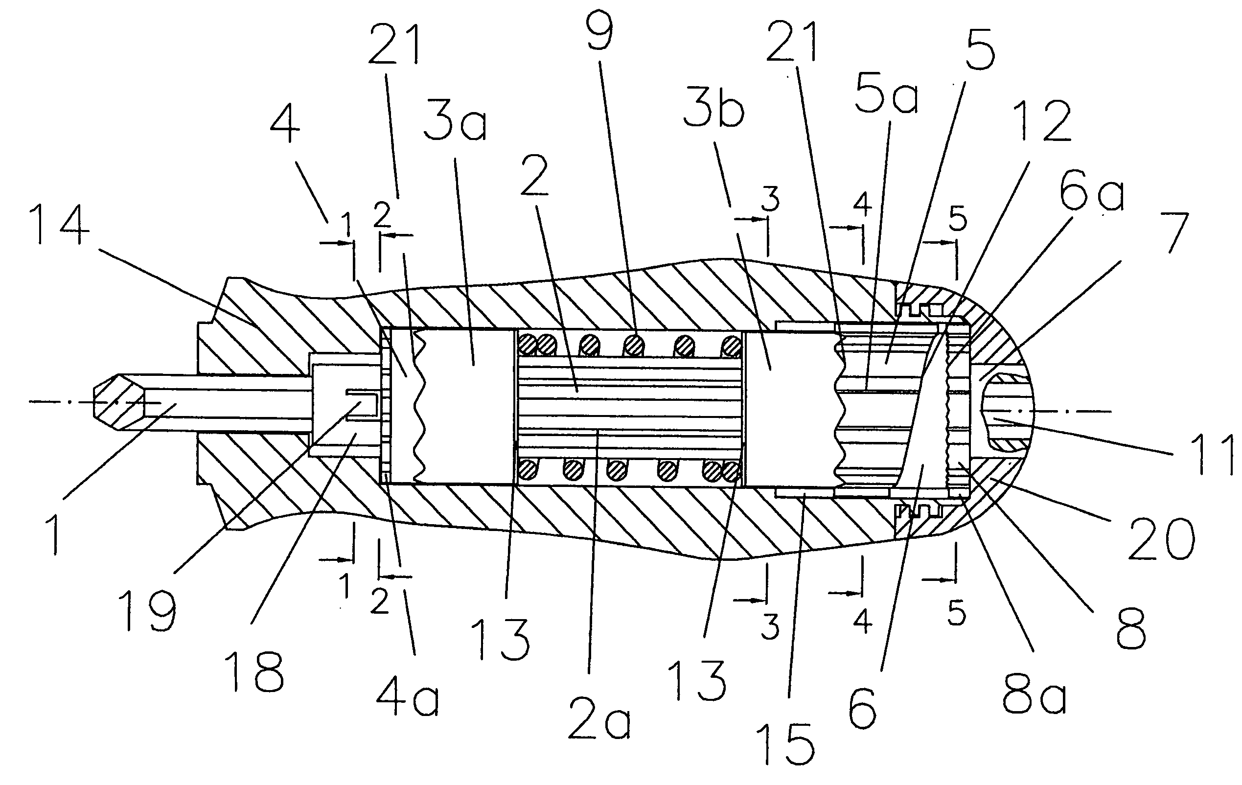
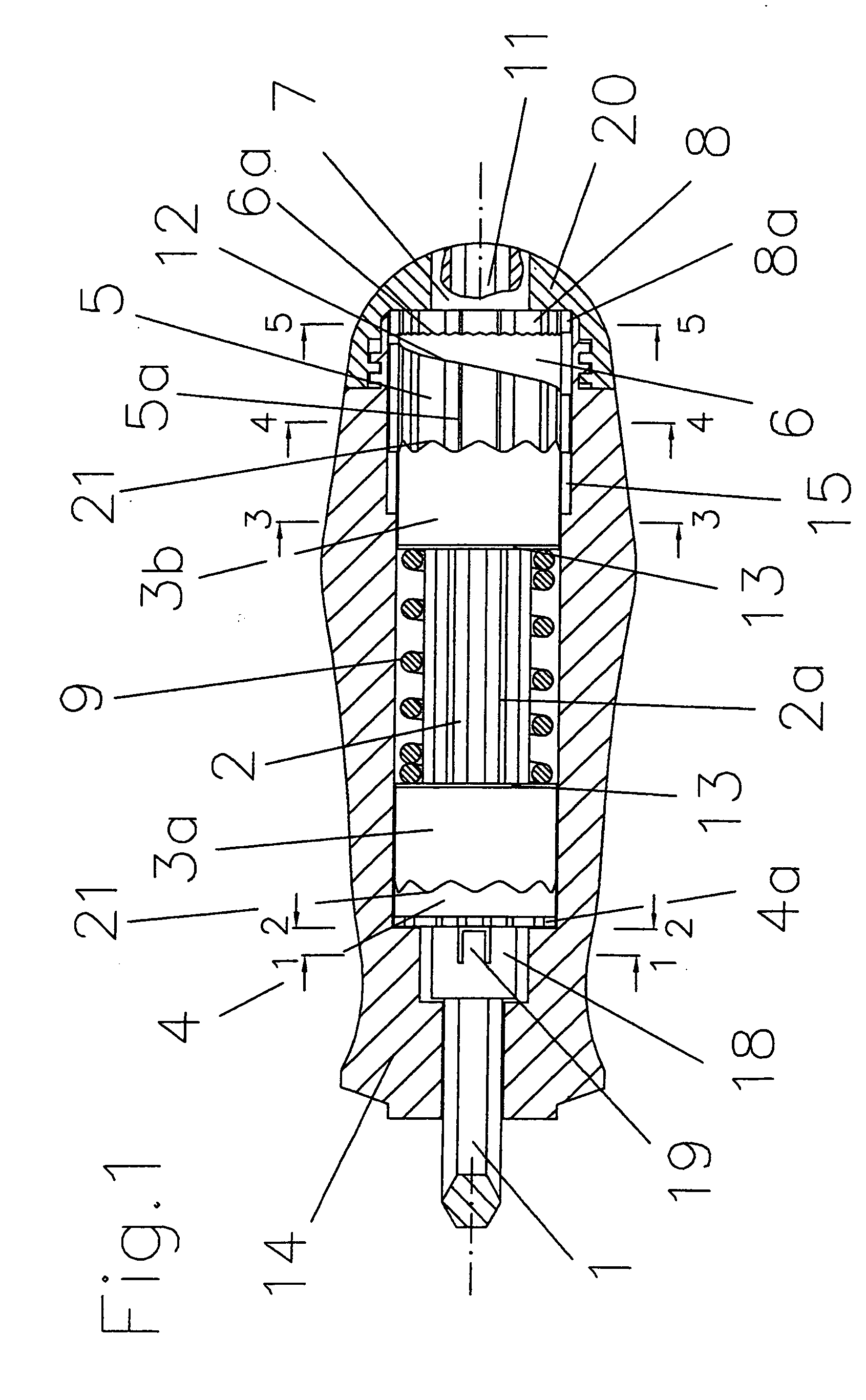
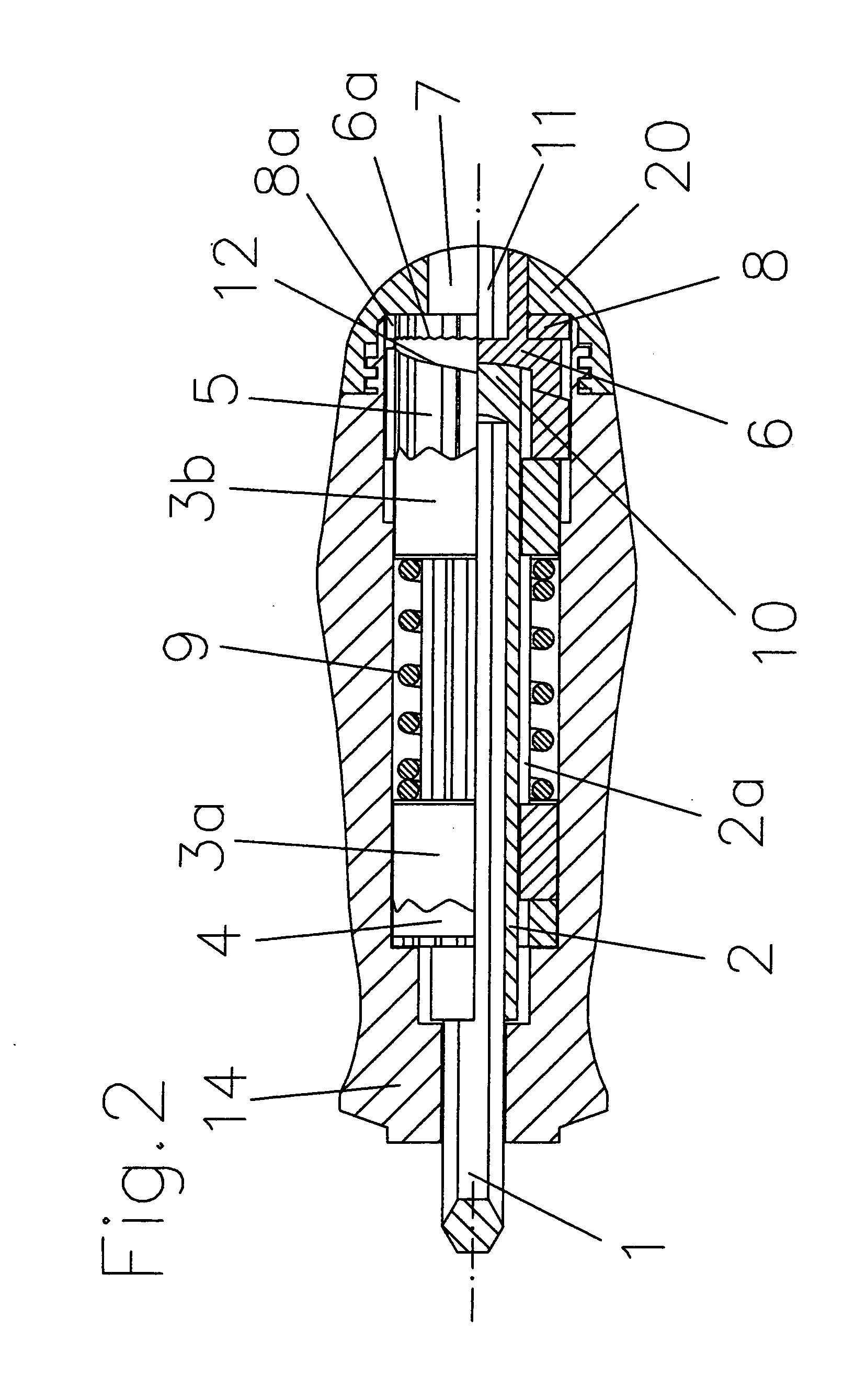
[0040] As FIG. 1 and FIG. 2 show the screwing-tool according the invention consists of a shank (1) with a non-circular cross-section profile, for example a hexagon profile, seated in the driver-shaft (2) and extending up to near the end of the teeth-shaft said shank (1) may be part of a screwdriver blade or of a holding device for screwdriver bits or for sockets. The driver-shaft (2) is profiled at it's circumference with a gear (2a) over almost the full length, the teeth having preferably a rectangular profile. The first sockets (3a, 3b) are assembled on the driver-shaft (2). With their cylindrical surface the first sockets (3a, 3b) serve also as radial bearing element of the whole torque-limiting mechanism by contacting rotateably the wall of the hollow in the handle (14), said hollow being shut by the cap (20). With an inner radial gear in their boring (3d in FIG. 5) the first sockets engage into the gearing (21) of the driver-shaft (2). At one front-side the first sockets (3a, 3...


PUM


Abstract

A screwing-tool with a device to adjust transmitted torque consists of a handle to introduce a torque to the device, which is borne in the hollow of the handle and a driver-shaft as outpout element of the torque. On the driver-shaft inside the handle two separate couplings are assembled, between them a compression spring exerting a spring force onto the two couplings. Each coupling consist of a first and second socket engaging each other by gearings at their opposing faces. The maximum torque at which the torque-transmission will be interrupted cab be adjusted in that way, that by an adjustment-element the distance between the couplings can be changed resulting in a change of the tension of the spring exerting a load on the couplings. The teeth of the gearings slide and the sockets rotate relatively to each other and interrupt the torque-transmission if a pre-adjusted torque is exceeded.

Description

BACKGROUND OF THE INVENTION [0001] The Invention concerns a screwing-tool / screwdriver with a device to adjust a pre-selected maximum torque at which the transmission of torque from the handle to a screwdriver-shank will be interrupted. [0002] Screwing-Tools with a device of that kind are known in different systems, in application at hand screwdrivers and power tools. [0003] Of special interest under the aspect of the invention are such systems at which the torque is transmitted from hand of the user through the handle of the tool to the shank of a screwdriver-blade. Systems which have to be considered in relation to the system according invention are described in their construction and function as follows: [0004] A screwdriver according U.S. Pat. No.5,746,298 with an adjustable torque limiting device is complicated in the construction of the torque transmitting coupling, which is made of metal. In the handle a rotateable shank is borne of which one end section is hexagon shaped in i...

Claims


Application Information

Patent Timeline
IPC IPC(8): B25B23/157A61B17/00A61B17/88A61B19/00B25B15/02B25B23/00B25B23/142B25G1/04B25G1/12B25G3/18
CPCA61B17/8875A61B2017/00464A61B2019/301B25B15/02B25G3/18B25B23/1427B25G1/046B25G1/125B25B23/0042A61B2090/031
Inventor BUBEL, RAINER
Owner FELO WERKZEUGFAB HOLLAND LETZ
Learn More