
Fault tolerant control system for multi-phase permanent magnet assisted synchronous reluctance motors

a technology of synchronous reluctance and fault tolerance, which is applied in the direction of electronic commutation motor control, motor/generator/converter stopper, dynamo-electric converter control, etc., and can solve the problems of reducing torque, affecting the operation of the motor, and not cost-effectively

Active Publication Date: 2016-01-28
THE UNIVERSITY OF AKRON
View PDF4 Cites 46 Cited by
  • Summary
  • Abstract
  • Description
  • Claims
  • Application Information

AI Technical Summary

Benefits of technology

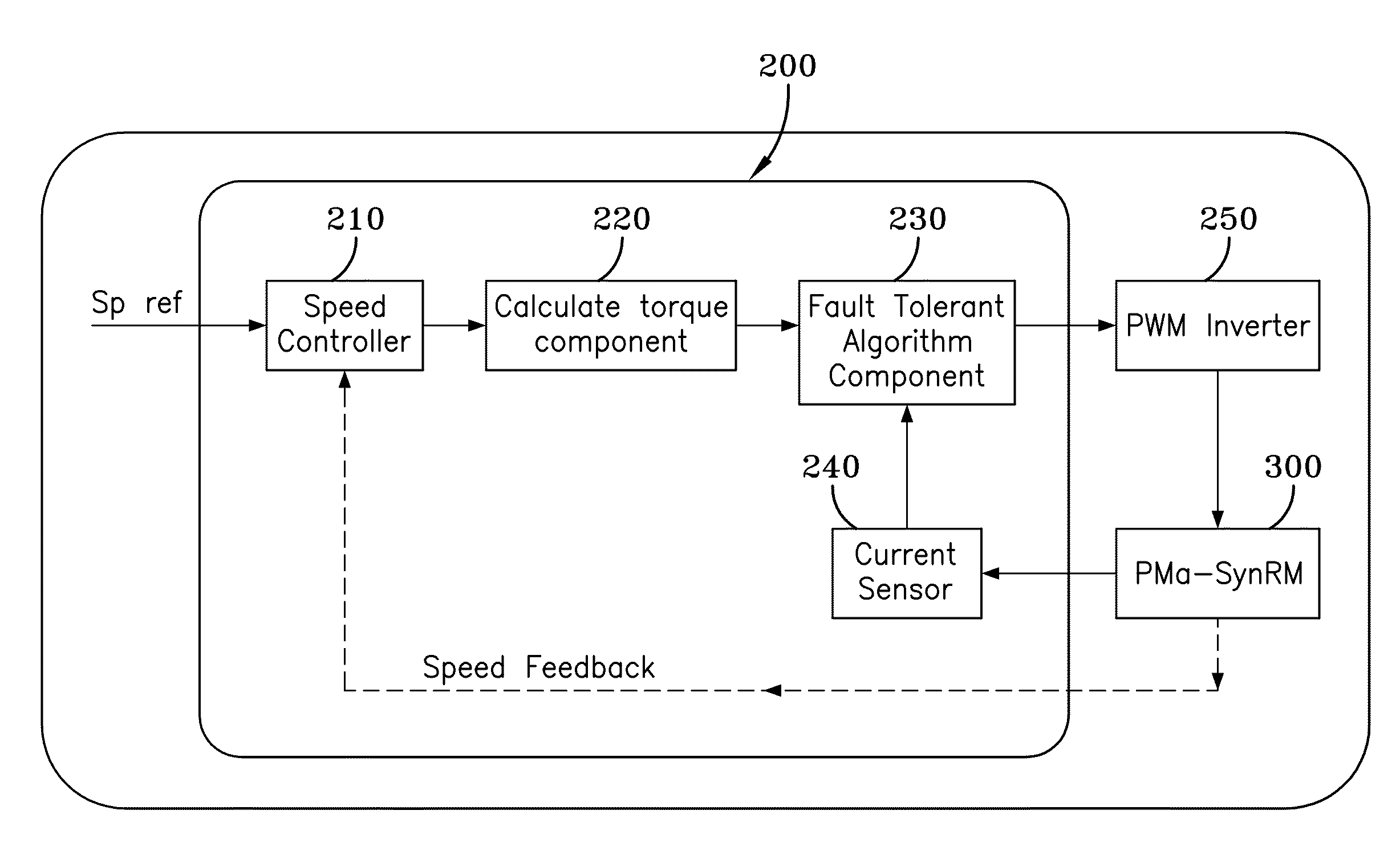
The present invention provides a method for controlling a multi-phase permanent magnet assisted synchronous reluctance motor that can identify and isolate a faulty phase and adjust the phase current amplitude and angle to deliver maximum torque output. The control system includes a speed controller, torque calculation component, fault tolerant algorithm component, and current sensor. The technical effect of the invention is to improve the reliability and efficiency of the multi-phase permanent magnet assisted synchronous reluctance motor during fault conditions.

Problems solved by technology

For example, some control techniques utilize a control system that includes redundant phases in the inverter side or additional machines / motors in parallel to continue motor operation when one motor experiences a fault, which is not cost effective.
However, by increasing the phase current significantly may cause critical machine / motor parameters of the PMa-SynRM to change, such as inductance, which is prone to going into the saturation region.
Furthermore, the operation of the PMa-SynRM motor with such increased phase currents may lead to decreased torque, lowered efficiency, and increased operating temperature, etc.
Also, the higher amount of phase current that is to be applied to the motor requires it to have a higher rated design, which may not be cost effective.
Moreover, under such conditions, the motor would not be capable of being operated for a long duration.
However, the application of this technique is limited where priority is given to obtain higher torque.

Method used


Image

  • Fault tolerant control system for multi-phase permanent magnet assisted synchronous reluctance motors
  • Fault tolerant control system for multi-phase permanent magnet assisted synchronous reluctance motors
  • Fault tolerant control system for multi-phase permanent magnet assisted synchronous reluctance motors

Examples


Embodiment Construction

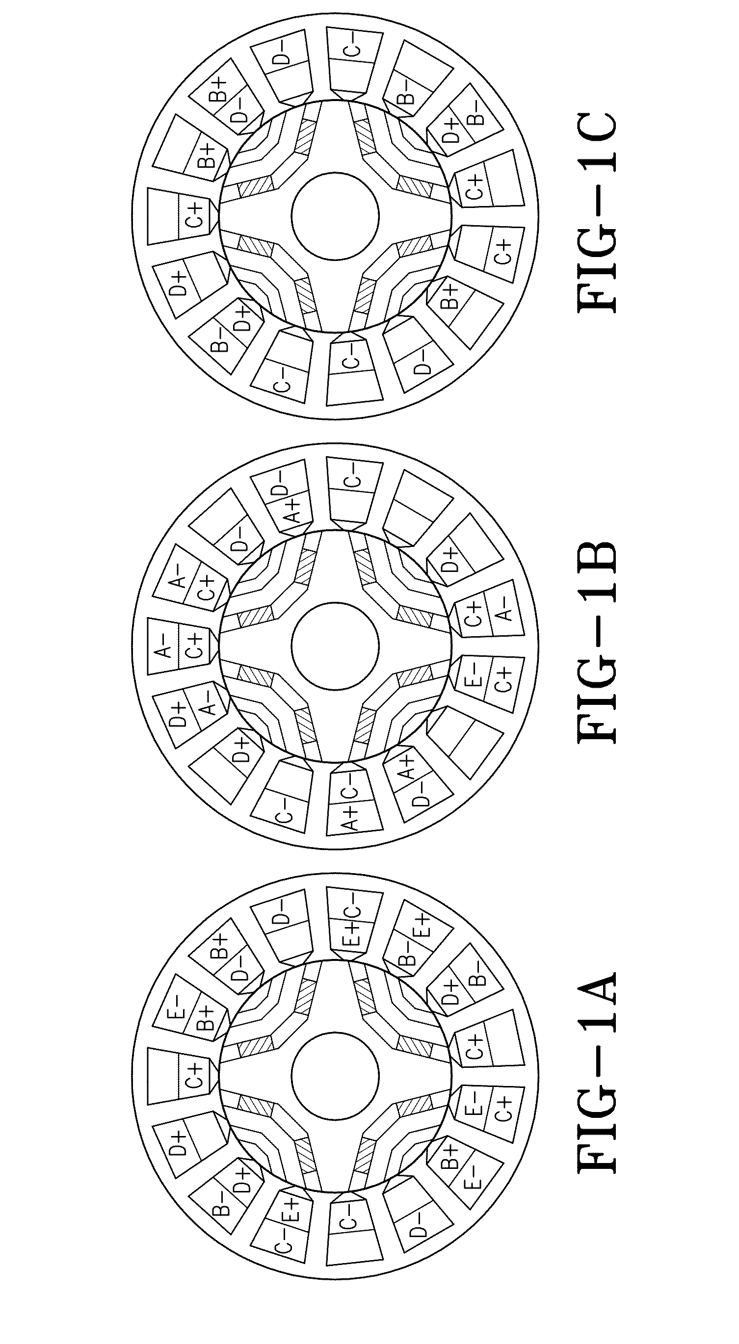
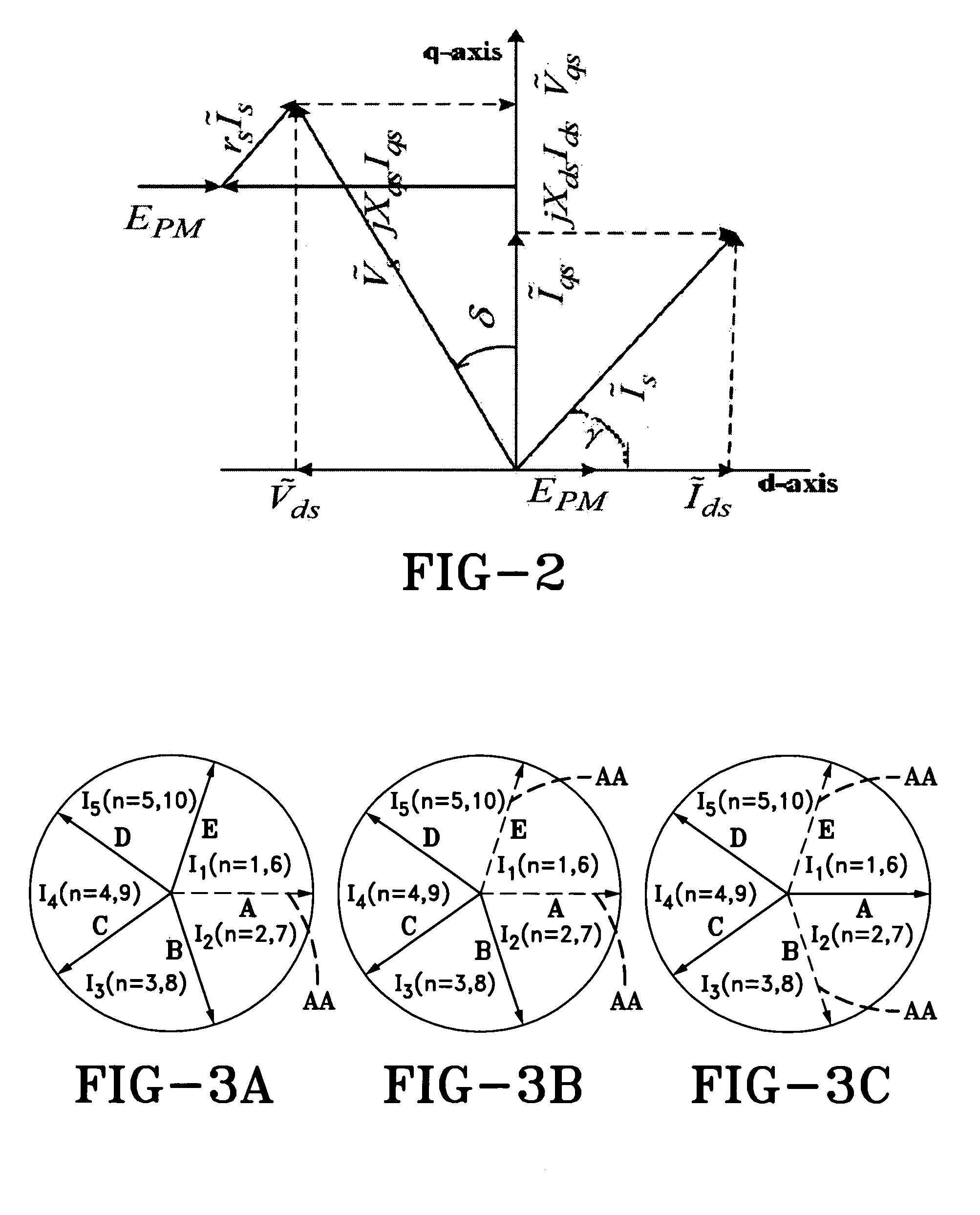
[0036]The present invention provides a control system for a multi-phase permanent magnet assisted synchronous reluctance motor (PMa-SynRM). It should be appreciated that for the purposes of the following discussion, the multi-phase permanent magnet assisted synchronous reluctance motor (PMa-SynRM) includes five-phases, however the control system of the present invention may be used with a multi-phase permanent magnet assisted synchronous reluctance motor (PMa-SynRM) having any number of phases. Before discussing the details of the PMa-SynRM motor control system of the present invention, a brief introduction to the operation and mathematical representation of the operating parameters of the PMa-SynRM motor will be presented to facilitate the understanding of the reader.

1. Five-Phase Motor Model Under Fault Conditions

[0037]To evaluate the control system of the present invention, an FEA (finite element analysis) model of a faulty multi-phase permanent magnet assisted synchronous reluct...


PUM


Abstract

A fault tolerant control system for a multi-phase permanent magnet assisted synchronous reluctance motor utilizes vector control to provide safe operation under various phase loss fault conditions. Specifically, the vector control of the present invention utilizes a fault tolerant algorithm that receives a torque input and an electrical current feedback signal from the motor. Thus, in the presence of a fault condition, the vector control applies the optimal torque angle to the motor, while reducing the phase currents to an optimized value to lessen the saturation effect in the motor, so as to ensure that the motor delivers maximum torque output in the presence of such faults. As such, the control system allows the motor to operate safely with high reliability, which is highly desirable, such as in electric vehicles and the aerospace industry.

Description

CROSS-REFERENCE TO RELATED APPLICATION[0001]This application claims the benefit of U.S. Provisional Application No. 62 / 023,333 filed Jul. 11, 2014, the contents of which are incorporated herein by reference.TECHNICAL FIELD[0002]Generally, the present invention relates to control systems for multi-phase synchronous reluctance motors. Particularly, the present invention relates to a fault tolerant control system for multi-phase synchronous reluctance motors. More particularly, the present invention relates to a fault tolerant control system for multi-phase synchronous reluctance motors that optimize the amplitude and angle of the phase currents applied to the motor, so as to maximize the amount of torque that the motor can generate when one or more motor phases are under a fault condition.BACKGROUND OF THE INVENTION[0003]A substantial amount of research has been performed to develop a reliable control for an electric motor or machine for use in critical service applications, such as i...

Claims


Application Information

Patent Timeline
Patent Type & Authority Applications(United States)
IPC IPC(8): H02P29/02H02P25/08
CPCH02P25/08H02P29/021H02P25/22H02P29/032
Inventor CHOI, SEUNGDEOGARAFAT, AKM
Owner THE UNIVERSITY OF AKRON
Learn More