Hybrid system control method

a hybrid system and control method technology, applied in process and machine control, battery/fuel cell control arrangement, instruments, etc., can solve problems such as inability to reduce shock, and achieve the effect of reducing reducing the shock when changing the clutch element to the forward sta

Active Publication Date: 2010-12-09
BOSCH CORP
View PDF45 Cites 54 Cited by
  • Summary
  • Abstract
  • Description
  • Claims
  • Application Information

AI Technical Summary

Benefits of technology

[0014]Thus, before the clutch element is engaged, a pseudo accelerator stroke position signal that is smaller than the actual accelerator stroke position is inputted to the variable speed ratio control means, so the variable speed ratio control means sets the variable speed means to a higher gear side before engagement of the clutch element. In this manner, the rotational velocity of the input shaft of the variable speed means moves to a lower speed side and its difference with the rotational velocity of the engine decreases. Consequently, shock when engaging the

Problems solved by technology

According to this hybrid vehicle, when the vehicle is stopped, the hybrid vehicle normally performs idling stop and then starts moving when accelerator pedal operation is performed by the driver, but because engine running efficiency when the hybrid vehicle starts moving is low, the hybrid vehicle starts moving by drive force supplied from the motor as long as it is not suddenly accelerated and continues traveling by the motor until a predetermined velocity or a predetermined required drive force is reached.
However, the control principle described above that predicts the transmittable maximum torque determined b

Method used


Image

  • Hybrid system control method
  • Hybrid system control method
  • Hybrid system control method

Examples


Embodiment Construction

[0056]Embodiment of the present invention will be described below with reference to the drawings.

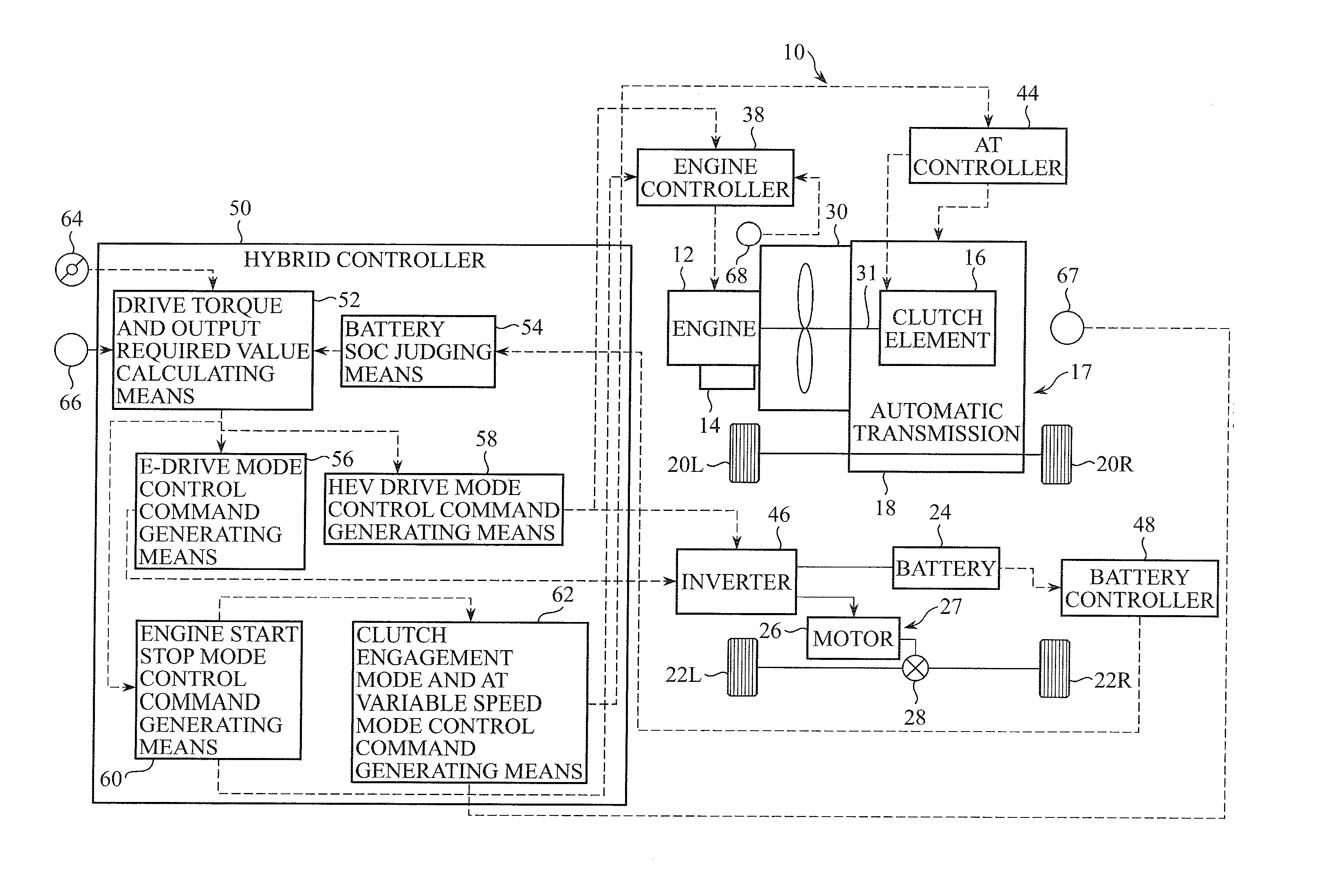
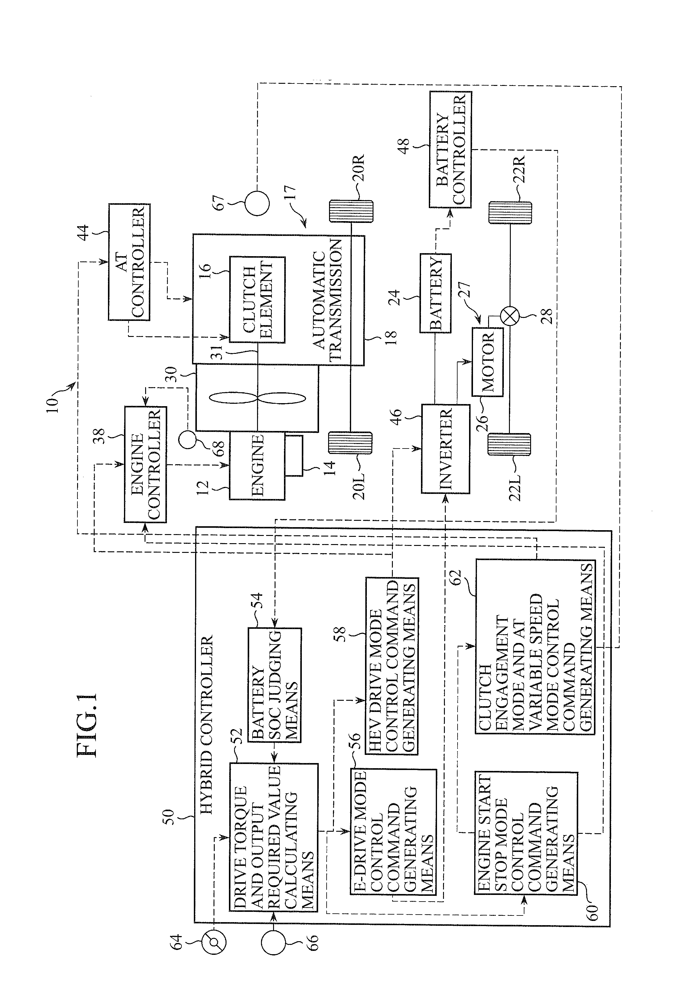
[0057]In FIG. 1, there are shown a vehicle 10 to which a hybrid system control method pertaining to a first embodiment of the present invention is applied and a control system of the vehicle 10 that enables control of the hybrid system. The vehicle 10 is a four-wheel drive hybrid vehicle where an electric axle unit is placed on a driven wheel axle of an existing two-wheel drive vehicle and which is configured by minimum vehicle alteration, and the vehicle 10 is equipped with an internal combustion engine 12, a starter motor 14 for starting up the engine 12, a first drive system 17 for transmitting drive force of the internal combustion engine to an axle of front wheels 20L and 20R, a battery 24, and a second drive system 27 for supplying electric power to an axle of rear wheels 22L and 22R.

[0058]The first drive system 17 is equipped with a torque converter 30 and an automatic variable sp...


PUM


Abstract

To enable a smooth transition from motor travel to hybrid travel despite the situation-of-charge of a battery and reduce shock at the time of engagement of a clutch element.
A hybrid system uses a state map 70 for deciding target torques of an engine and a motor on the basis of an accelerator stroke position, a vehicle velocity and a battery state-of-charge SOC. In the map 70, there are defined a motor maximum torque line that demarcates a motor upper limit torque that changes depending on the SOC and a motor margin torque line that is a predetermined margin lower than the motor maximum torque line. When the position on the map determined by the accelerator stroke position, the vehicle velocity and the battery state-of-charge is below the margin torque line, the hybrid system performs electric travel, and when the position on the map is on or above the margin torque line, the hybrid system initiates engine startup processing, and when the position on the map becomes a torque position exceeding the maximum torque line, the hybrid system sets target torques of the engine and the motor in order to achieve a torque corresponding to the accelerator stroke position.

Description

TECHNICAL FIELD[0001]The present invention pertains to a hybrid system control method applied to a hybrid vehicle and particularly relates to an axle-split hybrid system control method.BACKGROUND ART[0002]In JP-A-2006-160104, there is disclosed a hybrid vehicle having a configuration where a transmission and a motor are always coupled to a front wheel axle, an engine is coupled via a clutch to the front wheel axle, and another electric motor is always coupled to a rear wheel axle. According to this hybrid vehicle, when the vehicle is stopped, the hybrid vehicle normally performs idling stop and then starts moving when accelerator pedal operation is performed by the driver, but because engine running efficiency when the hybrid vehicle starts moving is low, the hybrid vehicle starts moving by drive force supplied from the motor as long as it is not suddenly accelerated and continues traveling by the motor until a predetermined velocity or a predetermined required drive force is reache...

Claims


Application Information

Patent Timeline
IPC IPC(8): G06F19/00B60L50/16B60W10/10
CPCB60K6/365B60L58/12B60K6/52B60K6/547B60L15/2045B60L2210/40B60L2240/12B60L2240/423B60L2240/441B60L2240/443B60L2240/486B60L2270/145B60W10/02B60W10/06B60W10/08B60W10/115B60W20/00B60W2510/0638B60W2510/1005B60W2510/1015B60W2510/244B60W2520/10B60W2540/10B60W2550/148B60W2710/0666B60W2710/083Y02T10/6221Y02T10/6265Y02T10/6286Y02T10/7077Y02T10/7283Y02T10/48B60W2050/0026Y02T10/7241Y02T10/7044Y02T10/7005Y02T10/705B60W20/40Y02T10/70Y02T10/645B60W20/13B60L50/16B60K6/48B60W2552/40Y02T10/40Y02T10/62Y02T10/64Y02T10/7072Y02T10/72
Inventor IMASEKI, TAKASHI
Owner BOSCH CORP
Why Eureka
Try Eureka