
Device for numerically displaying torque of torque wrench having a preset maximum torque

a torque wrench and torque technology, applied in the field of torque wrenches, can solve the problems of low precision and trouble, poor precision, complicated components,

Inactive Publication Date: 2006-02-21
IND TECH RES INST
View PDF4 Cites 48 Cited by
  • Summary
  • Abstract
  • Description
  • Claims
  • Application Information

AI Technical Summary

Benefits of technology

The present invention is a torque wrench with a preset maximum torque. It includes a hollow cylindrical handle, an enclosed box portion at the front, a torque measurement assembly at the back, and a numeric display device. The torque measurement assembly has a trigger member and a signal generator. The trigger member is connected to the rear of the enclosed box portion, while the signal generator is connected to the front of the trigger member. The setting assembly is mounted at the back of the handle and is connected to the signal generator. It can move for pushing the signal generator. The invention allows for easy monitoring of the amount of torque being exerted by the wrench and ensures that the preset maximum torque is always maintained.

Problems solved by technology

However, such mechanism has the drawbacks of being low in precision and trouble prone.
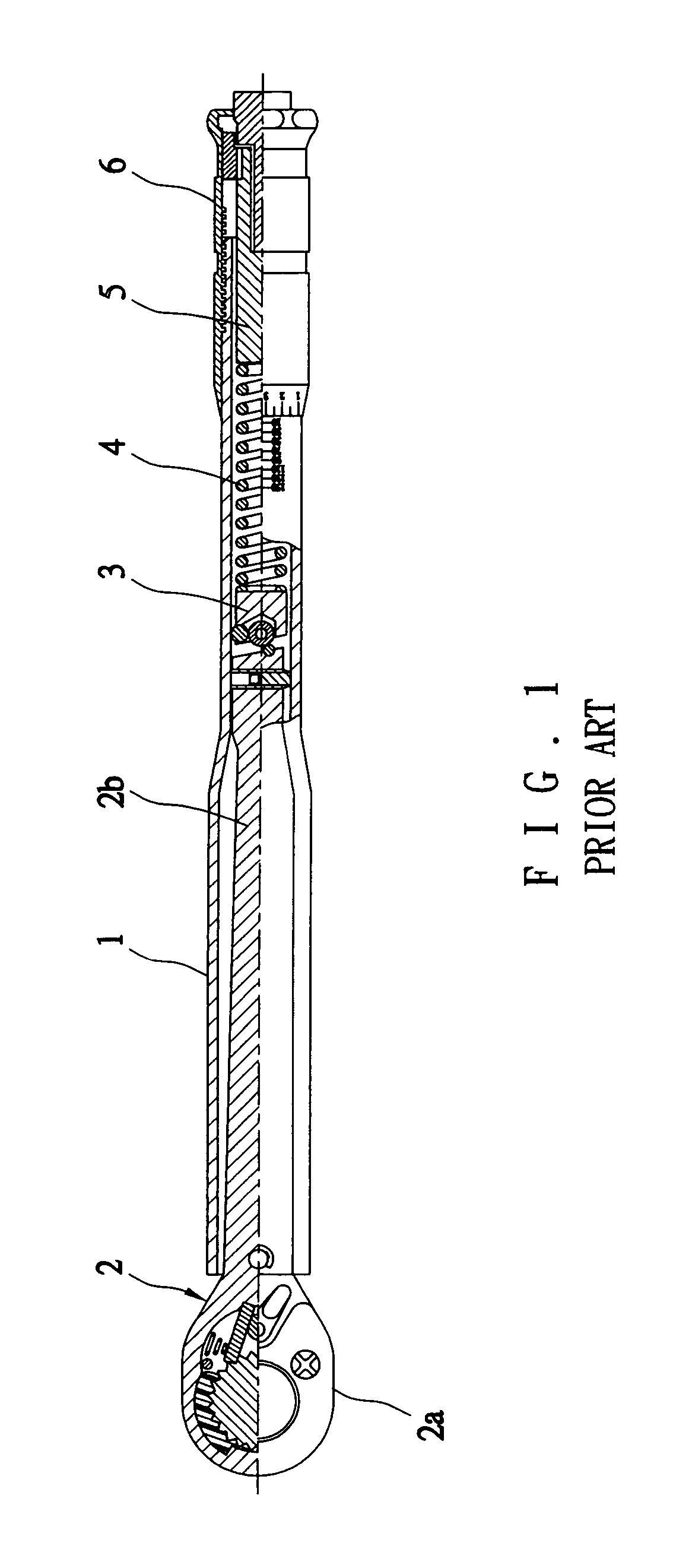
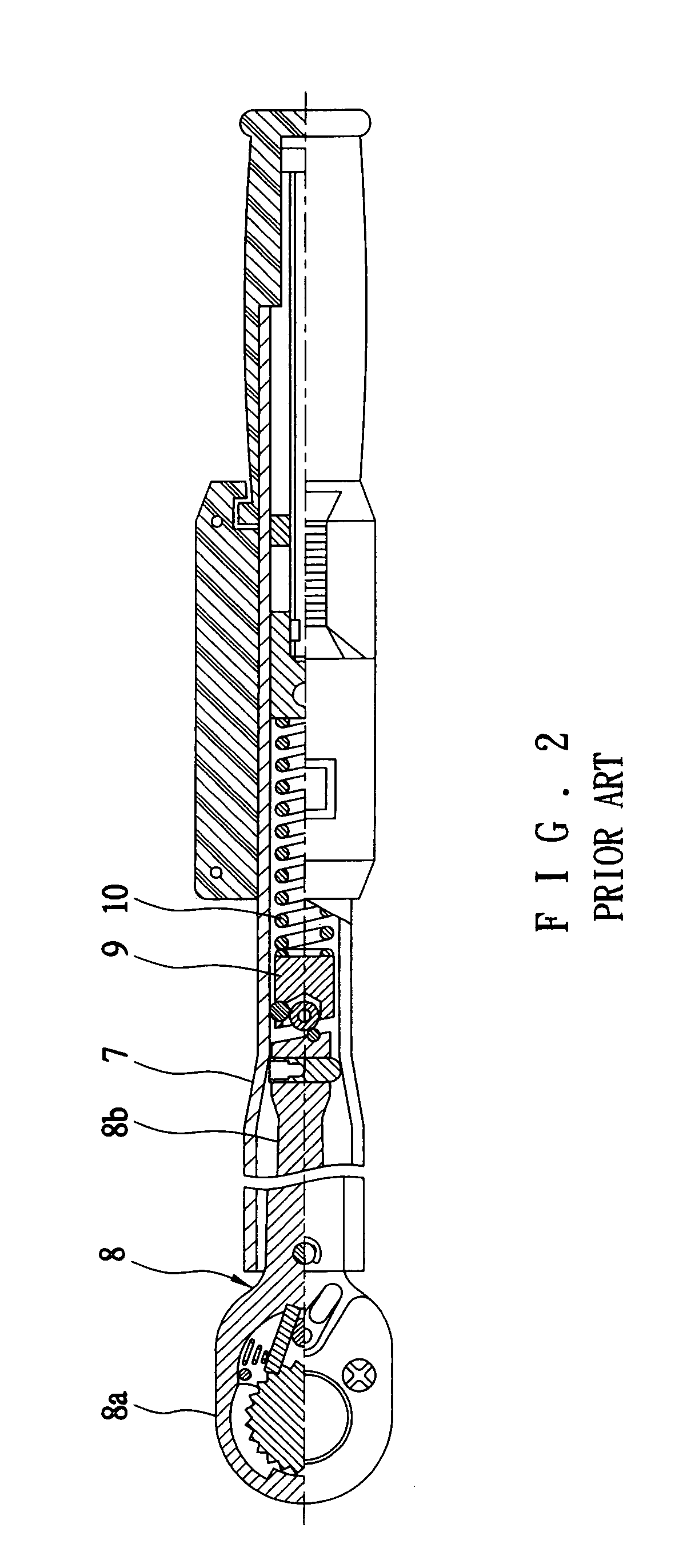
However, such mechanism still has the drawbacks of having complicated components and poor precision if the movement of the sliding member 16 is not smooth, elasticity of the spring 10 is fatigued, or a contact between the trigger member 9 and the rear end of the bar 8b is loosened.
Above drawbacks may compromise the desired effect of automatically tripping the trigger member 9 when the amount of torque being exerted by the wrench has reached the preset maximum torque.

Method used


Image

  • Device for numerically displaying torque of torque wrench having a preset maximum torque
  • Device for numerically displaying torque of torque wrench having a preset maximum torque
  • Device for numerically displaying torque of torque wrench having a preset maximum torque

Examples


Embodiment Construction

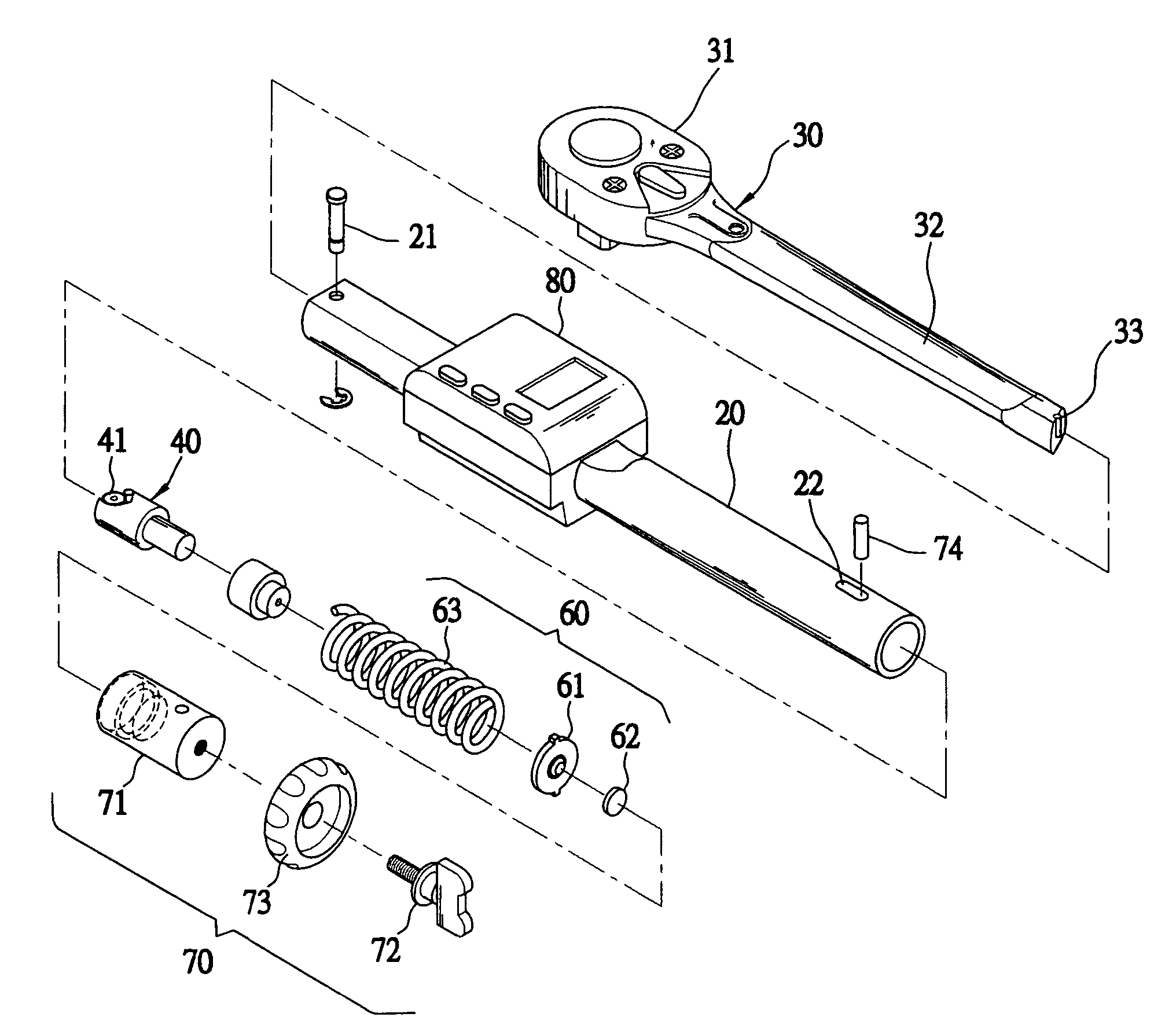
[0016]Referring to FIGS. 4 to 7, a torque wrench constructed in accordance with the invention is shown. The wrench comprises a hollow, cylindrical handle 20 including an elongated groove 22 adjacent a rear end, an enclosed box portion 30 at a forward end of the handle 20, the enclosed box portion 30 being releasably coupled to the handle 20 by driving a pin 21 through both apertures of the enclosed box portion 30 and the handle 20 to be fastened by a clip, the enclosed box portion 30 including a head 31, an elongate bar 32 extended into the handle 20, and an extension 33 at a rear end of the bar 32, a trigger member 40 including a top roller 41 at a front end in contact with the extension 33, a signal generator 60 including a forward spring 63 having a forward end biased against a rear end of the trigger member 40, a rear sensor 62, and an intermediate disc 61 having a forward side engaged with the spring 63 and a raised central portion at a rear side engaged with the sensor 62 wher...


PUM


Abstract

Disclosed is a torque wrench comprising a signal generator including a spring biased against a trigger member, a sensor, and a disc biased between the spring and the sensor, a setting assembly including a cylindrical member for receiving the disc and the sensor, a cap, a knob through the cap to threadably couple to the cylindrical member, and a sliding pin inserted through a groove on a handle into the cylindrical member for coupling, and a numeric display mounted around the handle. A maximum torque of the wrench can be preset by rotating the knob and shown on the display. Also, an amount of torque being exerted by wrench can be shown on the display. The wrench may trip when the amount of torque has reached the preset maximum torque.

Description

BACKGROUND OF THE INVENTION[0001]1. Field of the Invention[0002]The present invention relates to torque wrenches and more particularly to such a torque wrench having a numeric display for displaying a preset maximum torque and an amount of torque being exerted so that the wrench may stop tightening a thing (e.g., bolt, nut, etc.) automatically when the amount of torque has reached the preset maximum torque.[0003]2. Description of Related Art[0004]Torque wrenches are well known. For example, a prior torque wrench is shown in FIG. 1. The wrench comprises an elongated, hollow handle 1, an enclosed box portion 2 at a forward end of the handle 1, the enclosed box portion 2 including a head 2a and an elongate bar 2b extended into the handle 1, a trigger member 3 at a rear end of the bar 2b, a spring 4 having a forward end biased against a rear end of the trigger member 3, a rod 5 having a forward end biased by a rear end of the spring 4, and a rotatable cap 6 having internal threads adapt...

Claims


Application Information

Patent Timeline
Patent Type & Authority Patents(United States)
IPC IPC(8): B25B23/144B25B23/14B25B23/142B25B23/157B25B23/159
CPCB25B23/1427B25B23/1425
Inventor LI, MING-HUALIN, LI-HSIACHOU, MEI-CHIN
Owner IND TECH RES INST
Learn More