Multi-speed transmission

a transmission and multi-speed technology, applied in the field of transmissions, can solve the problems of inefficient or undesirable transmission weight and size, and conventional multi-speed dual-clutch transmissions that do not have the torque range and available gear ratios to be employed in commercial vehicles or trucks

Inactive Publication Date: 2009-02-05
GM GLOBAL TECH OPERATIONS LLC
View PDF3 Cites 74 Cited by
  • Summary
  • Abstract
  • Description
  • Claims
  • Application Information

AI Technical Summary

Problems solved by technology

While useful for its intended purpose, these conventional multi-speed dual clutch transmissions do not have the range of torque and available gear ratios necessary to be employed in commercial ...

Method used


Image

  • Multi-speed transmission
  • Multi-speed transmission
  • Multi-speed transmission

Examples


Embodiment Construction

[0029]The following description is merely exemplary in nature and is not intended to limit the present disclosure, application, or uses.

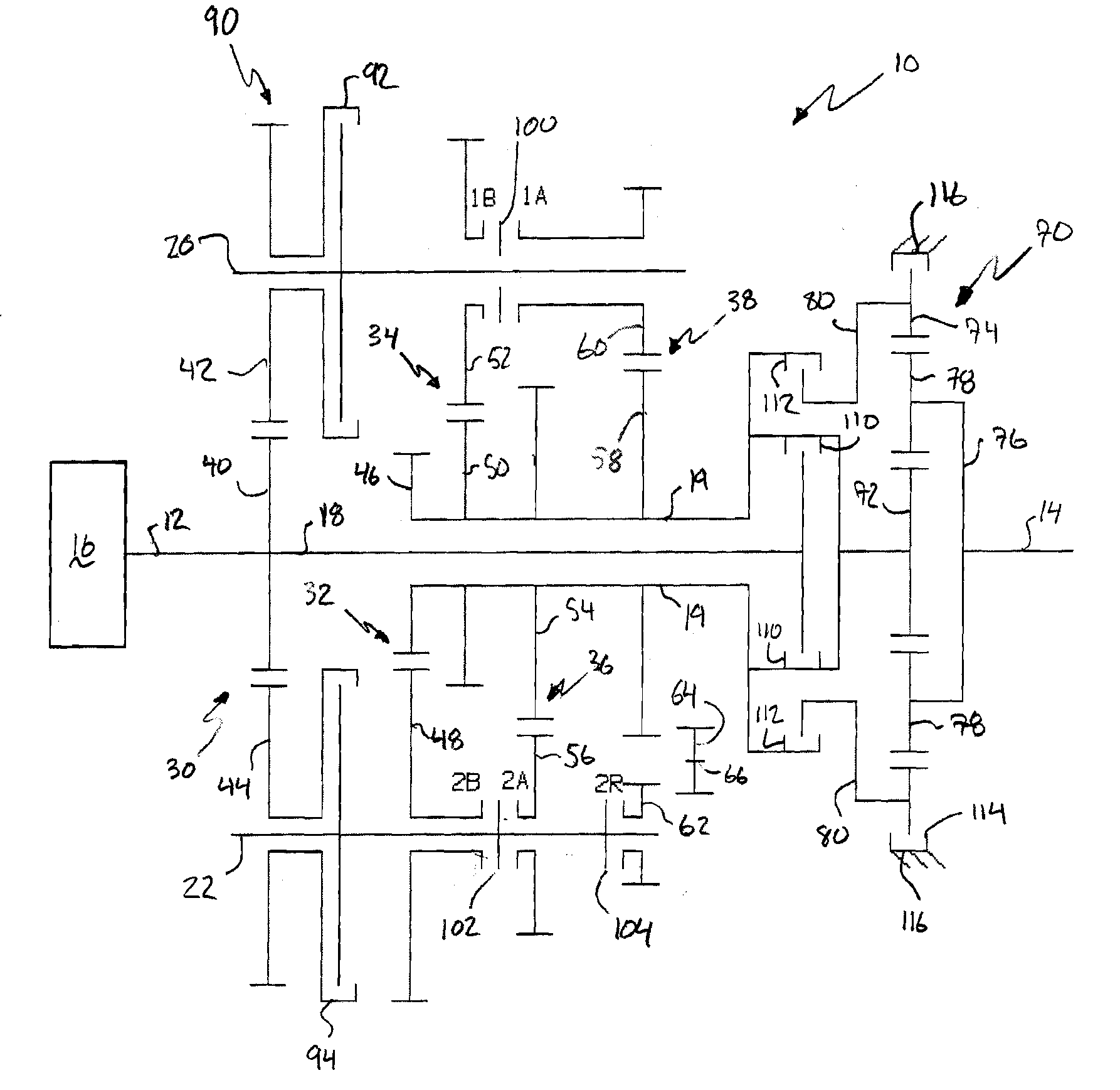
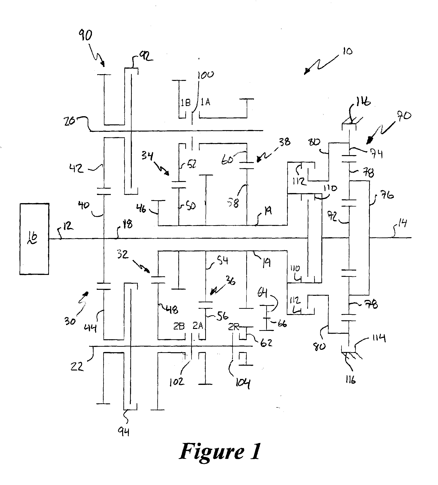
[0030]With reference to FIG. 1, a stick diagram presents a schematic layout of a multi-speed transmission for use in a motor vehicle, generally indicated by reference number 10. The transmission 10 is preferably a longitudinal dual clutch transmission (DCT). The transmission 10 includes an input shaft or member 12 and an output shaft or member 14. Those skilled in the art will appreciate that the input and output members 12, 14 may be components other than shafts without departing from the scope of the present invention. The input member 12 is continuously connected to a turbine of a torque converter 16. The output member 14 is continuously connected with a final drive unit or transfer case (not shown) in the motor vehicle.

[0031]The transmission 10 further includes intermediate shafts, countershafts, co-planar intermeshing gear sets, and selectively...


PUM


Abstract

A transmission is provided having an input member, an output member, a dual clutch assembly, two countershaft gearing arrangements, one planetary gear set, a plurality of interconnecting members, and a plurality of torque transmitting devices. Each of the countershaft gearing arrangements includes a plurality of co-planar gear sets. The torque transmitting devices include a combination of clutches, brakes, and synchronizers.

Description

FIELD[0001]The present disclosure relates to transmissions, and more particularly to a multiple speed transmission having a dual clutch assembly and dual countershafts.BACKGROUND[0002]The statements in this section merely provide background information related to the present disclosure and may or may not constitute prior art.[0003]A typical multi-speed, dual clutch transmission employs a plurality of clutches to achieve a plurality of forward and reverse gear ratios. These dual clutch transmissions are typically employed in front-wheel drive applications. Additionally, a slipping clutch is employed to transmit launch torque from an engine to the transmission in order to achieve a high power-to-weight ratio that is desirable in non-commercial vehicles.[0004]While useful for its intended purpose, these conventional multi-speed dual clutch transmissions do not have the range of torque and available gear ratios necessary to be employed in commercial vehicles or trucks. Additionally, the...

Claims


Application Information

Patent Timeline
IPC IPC(8): F16H1/22F16D11/14F16H37/00F16H47/08
CPCF16H3/006F16H3/0915F16H37/0833F16H2200/0052F16H2200/006Y10T74/19288F16H2200/0086Y10T74/19223Y10T74/19233Y10T74/19228F16H2200/0065
Inventor EARHART, DAVID EARLRASZKOWSKI, JAMES A.
Owner GM GLOBAL TECH OPERATIONS LLC
Why Eureka
Try Eureka