A premature release leads to engine speed
flare and a deeper torque hole, causing perceptible shift shock for a vehicle occupant.
A delayed release causes a tie-up of gear elements, also resulting in a deep and wide torque hole for inconsistent shift feel.
This conventional method does not ensure optimal off-going friction element release timing and therefore results in inconsistent shift feel.
When a release of the off-going friction element is initiated prematurely before the on-corning friction element develops enough torque, engine speed or
automatic transmission input shaft speed may rise rapidly in an uncontrolled manner.
This speed-based or slip-based approach often results in a hunting behavior between gear tie-up and engine flair, leading to inconsistent shift feel.
Furthermore, off-going friction element slip control is extremely difficult because of its high sensitivity to slip conditions and a discontinuity between static and dynamic frictional forces.
A failure to achieve a seamless slip control during the torque phase leads to undesirable shift shock.
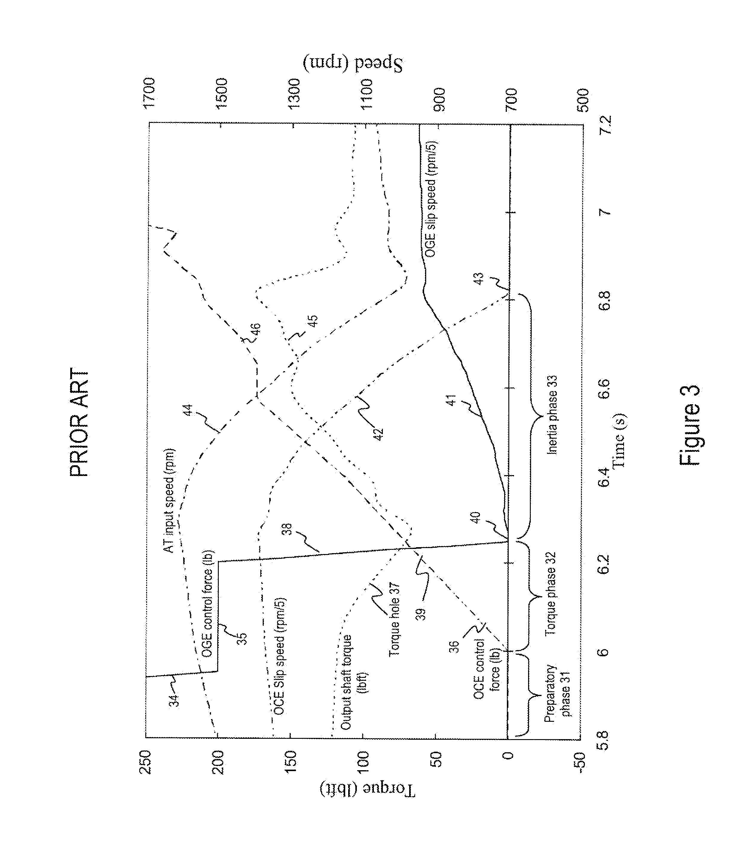
As a result of this interaction, the automatic transmission output shaft torque drops during the torque phase, which again creates a so-called “torque hole.” Before the one-way
coupling disengages, as in the case previously described, a large torque hole can be perceived by a vehicle occupant as an unpleasant shift shock.
A large torque hole can be perceived by a vehicle occupant as an unpleasant shift shock.
A large level of engine
flare can be audible to a vehicle occupant as unpleasant
noise.
Under certain conditions, this may lead to a torque oscillation 57 that can be perceptible to a vehicle occupant as unpleasant shift shock.
However, large on-coming friction element
control force 65 results in a
drag torque, lowering automatic transmission output shaft torque, creating a deep and wide torque hole 63.
A severe tie-up can be felt as a shift shock or loss of power by a vehicle occupant.
If these conditions are severe, they result in undesirable driving experience such as inconsistent shift feel or perceptible shift shock.
A deep torque hole may be perceived as an unpleasant shift shock.
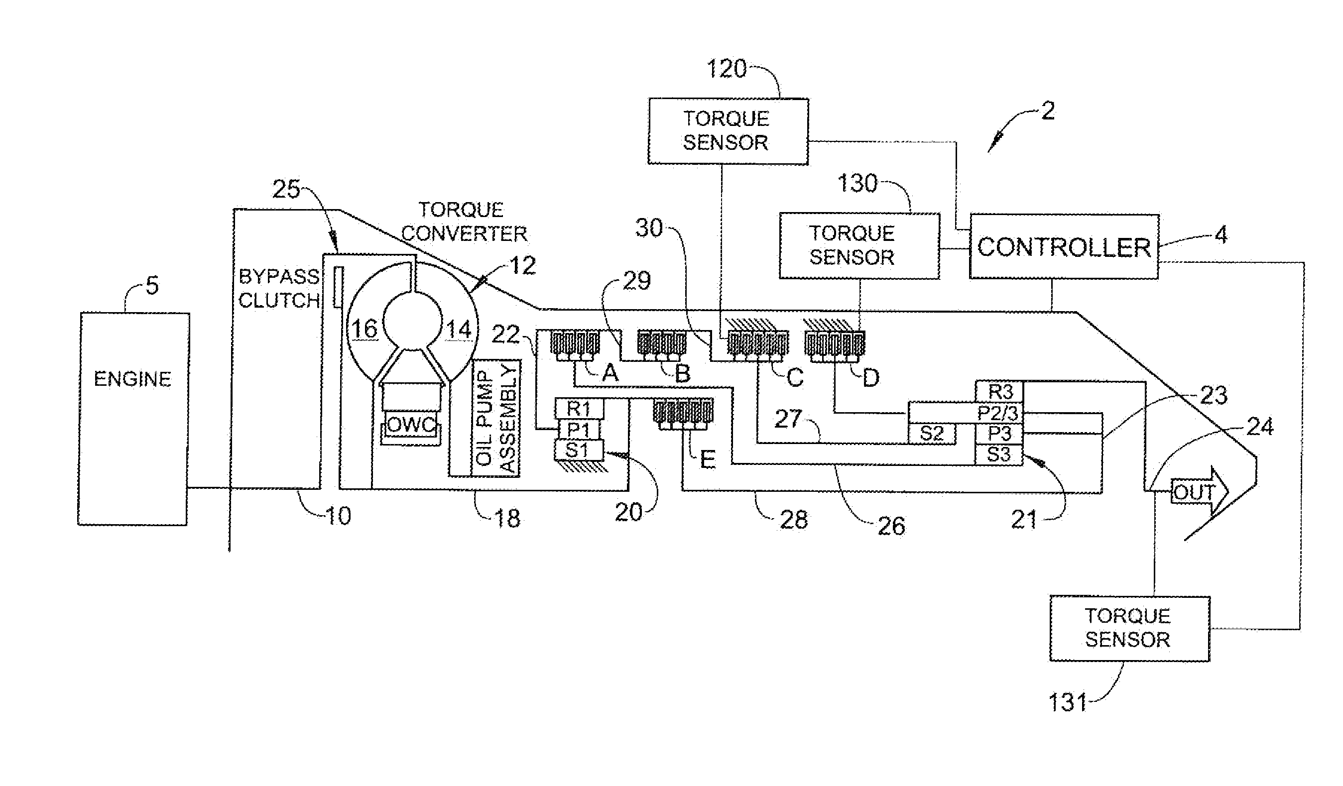
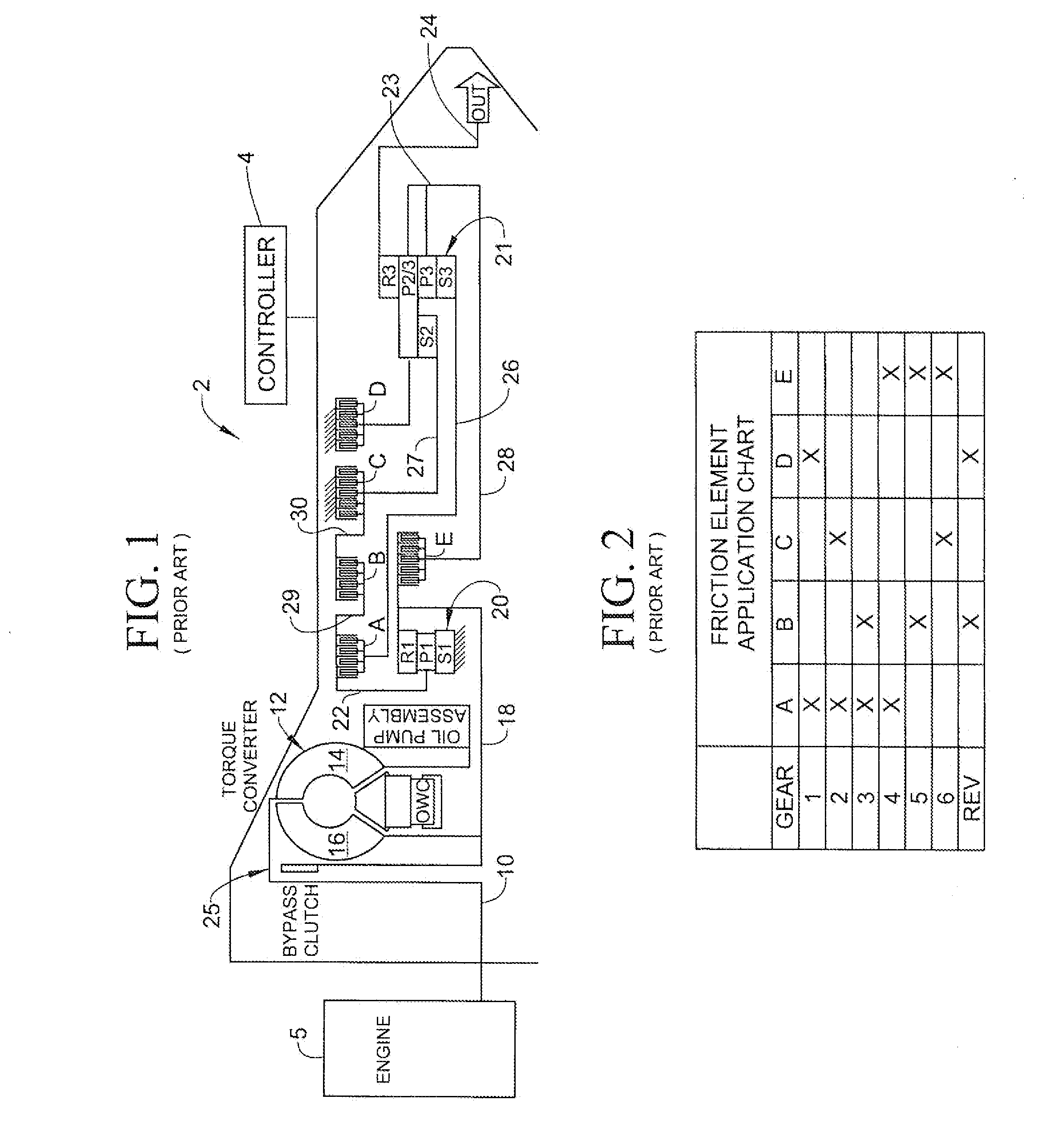
If a release of off-going friction element D is initiated prematurely before on-coming friction element C develops enough torque, engine speed or input shaft speed may rise rapidly in an uncontrolled manner.
In summary, a prior art methodology, which is based on an open-loop on-corning friction element control during a torque phase, cannot account for
control system variability and dynamically-changing shift conditions during the torque phase, resulting in inconsistent shift feel or unpleasant shift shock.
A pre-determined off-going friction element release timing with a pre-calibrated
control force profile cannot ensure an optimal timing under dynamically changing shift conditions, resulting in inconsistent shift feel or unpleasant shift shock.
The alternative approach to gauge off-going friction element release timing based on speed signals often results in a hunting behavior between gear tie-up and engine flair, leading to inconsistent shift feel.
Furthermore, off-going friction element slip control is extremely difficult because of its high sensitivity to slip conditions.
In addition, a large discontinuity exists between static and dynamic friction coefficients, introducing a large torque disturbance during an incipient slip control.
A failure to achieve a seamless off-going friction element slip control during the torque phase leads to undesirable shift shock.
The prior art that depends on an open-loop approach which may be based on speed measurements does not have any solution to the problem of consistently controlling torque passing through either a multiple disc
clutch or a
band brake and therefore is a need in the art for a transmission
control system that minimizes shift shock during a
gear ratio change that does not rely solely on traditional speed
signal measurement and instead relies on measured or estimated friction element load level in either a multiple plate
clutch or a
band brake during a torque phase of gear-ratio changing.

