Tubular connection floating shoulder ring

a shoulder ring and tubular connection technology, applied in the direction of hose connection, pipe-joint, fastening means, etc., can solve the problems of changing the performance requirements of the casing string, limited torque capacity of the connection, and inability to adapt well, so as to increase the ability of tubular connection to transmit torque and enhance the connection torque capacity

Inactive Publication Date: 2005-05-31
NABORS DRILLING TECH USA INC
View PDF13 Cites 13 Cited by
  • Summary
  • Abstract
  • Description
  • Claims
  • Application Information

AI Technical Summary

Benefits of technology

[0011]A floating shoulder ring has been invented for tubular connections. The present invention provides a means to substantially increase the ability of tubular connections to transmit torque. When placed internally between the pipe ends of a threaded and coupled pipe connection, the torque ring acts as a floating internal upset coupling shoulder capable of reacting compressive axial load between the pin ends and thus enhancing the connection torque capacity. The present invention is particularly useful as a means to upgrade the torque capacity of tapered couplings such as, for example, unmodified API buttress and round threaded and coupled connections, manufactured to industry standard tolerances, to meet the requirements of casing drilling applications. The ring is placed substantially coaxially in the coupling of the connection, between the pin ends of the joined tubulars.

Problems solved by technology

However, using casing to both drill and complete the well changes the performance requirements of the casing string, and more particularly the torque capacity of the casing connections, from those established through use within the historic methods of well construction.
These connections have limited torque capacity and are thus not well suited to the casing drilling application, but are readily available and relatively inexpensive.
However, these prior art couplings require modification of the standard API components or increased quality control and, therefore, substantially reduce the benefits of low cost and simplicity originally sought from using existing industry standard couplings and pins.
In addition, prior art couplings are in large part motivated by the desire to upgrade the pressure containment capacity of API connections and, as such, are not optimised to obtain upgraded torque capacity desired for casing drilling applications.

Method used


Image

  • Tubular connection floating shoulder ring
  • Tubular connection floating shoulder ring
  • Tubular connection floating shoulder ring

Examples


Embodiment Construction

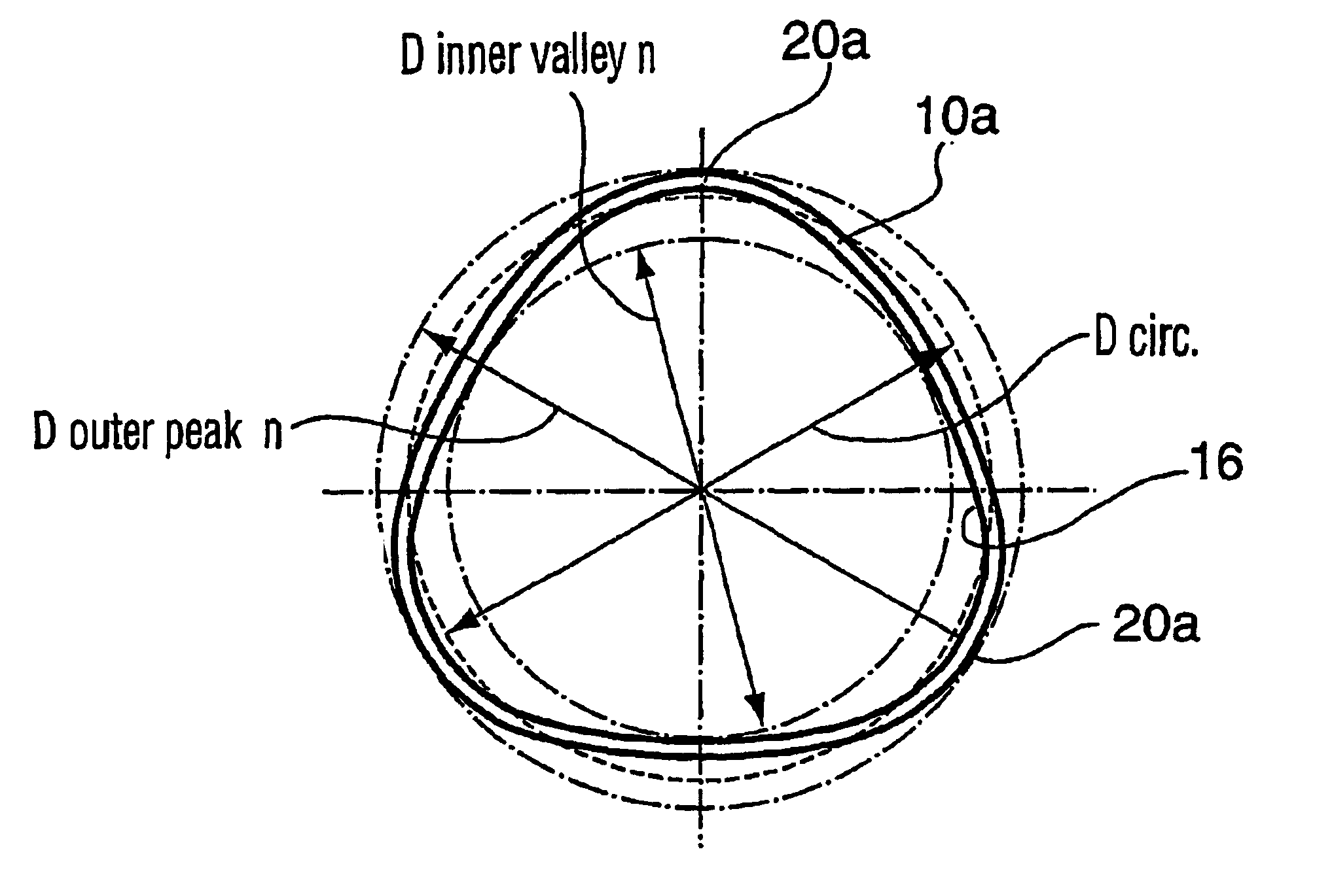
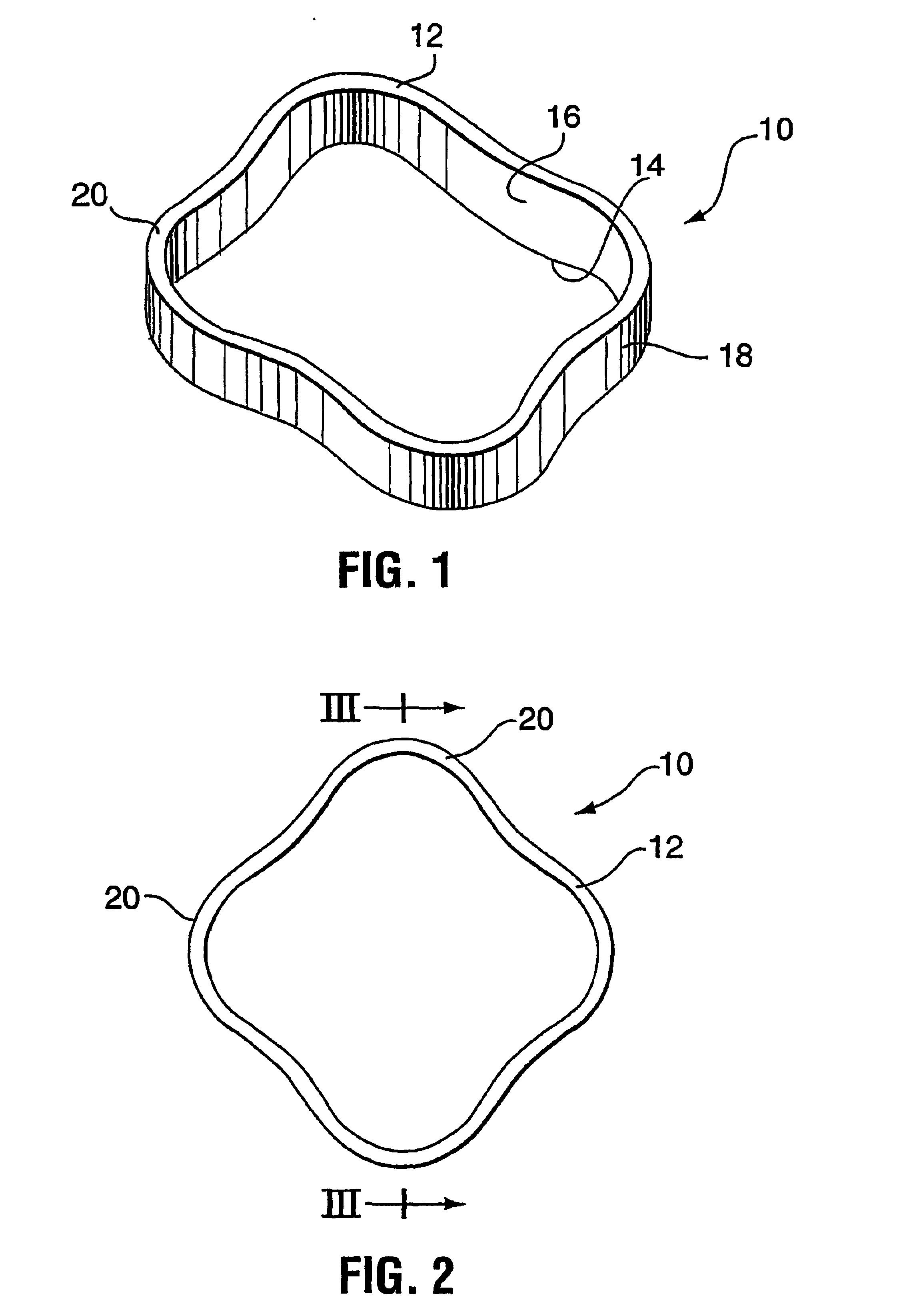
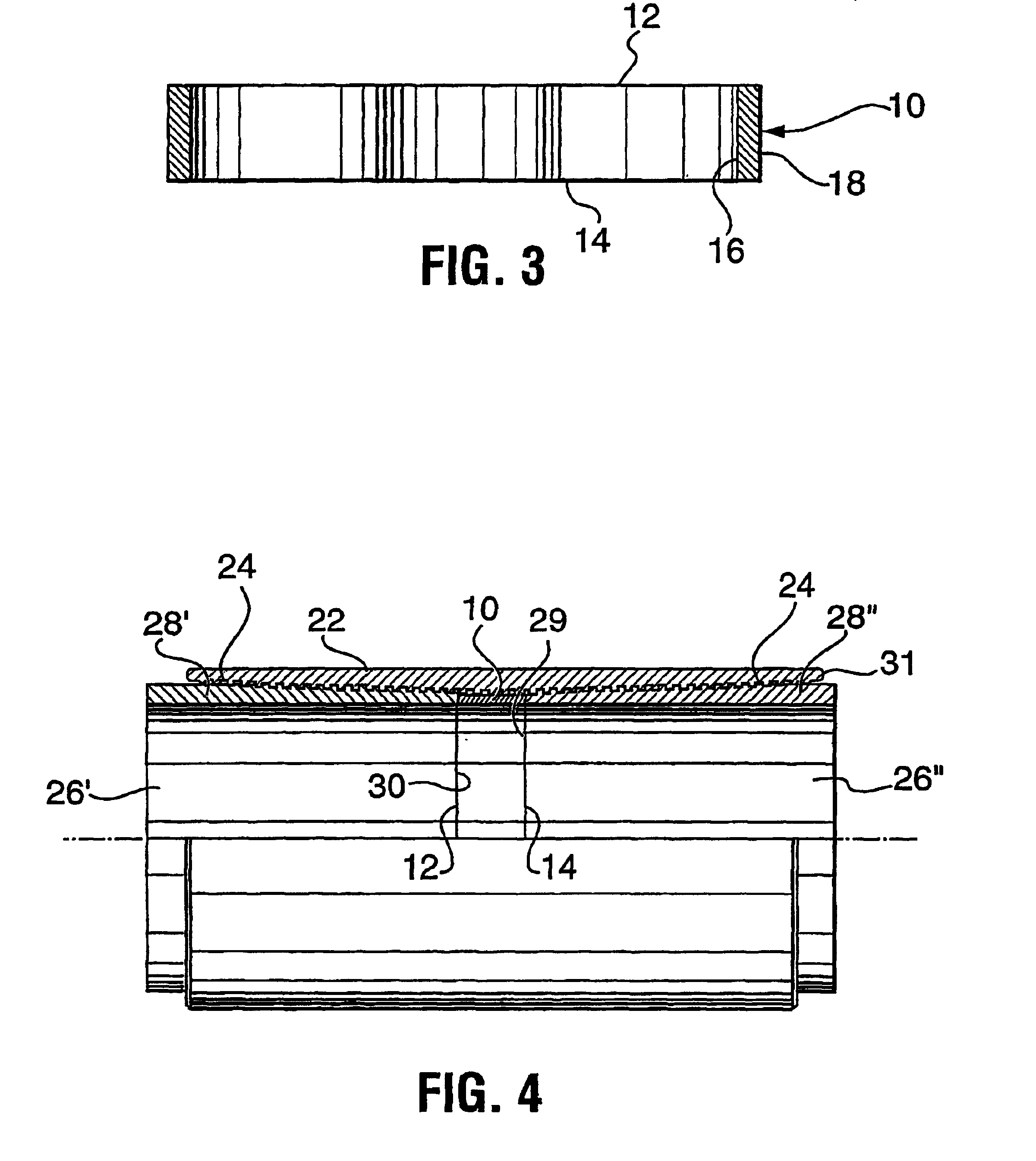
[0030]According to the present invention, a shoulder ring is provided for placement in a threaded and coupled connection, such as a standard API connection, joining two lengths or joints of tubulars. As shown in FIGS. 1 to 3 a shoulder ring 10 according to the present invention has a first end face 12, an opposite end face 14, an inner surface 16 adjacent a central opening and extending between the first end face and the opposite end face and an outer surface 18 extending between the first end face and the opposite end face. The ring has a substantially uniform cross sectional shape about its circumference. In particular, the thickness of the ring between the inner surface and the outer surface does not vary substantially about the ring, nor does the length of the ring between the first end face and the opposite end face. The ring's radius to the outer surface varies around its circumference to form four lobes 20. While four lobes are shown, it is to be understood that ring can have...


PUM


Abstract

A shoulder ring (10) for installing in the J-space between the installed pin ends within a coupling collar is taught having a body with a central opening therethrough, a first end face (12) on the body, an opposite end face (14) on the body, an inner surface (16) adjacent the central opening and extending between the first end face and the opposite end face and an outer surface (18) extending between the first end face and the opposite end face, the body having a substantially uniform cross sectional shape between the first end face, the opposite end face, the inner surface and the outer surface and the ring shaped such that its radius to the outer surface varies around the outer surface circumference to form a plurality of lobes (12).

Description

FIELD OF THE INVENTION[0001]The present invention relates to tube couplings and in particular, a floating shoulder ring for tube couplings.BACKGROUND OF THE INVENTION[0002]Tubulars used to drill and complete bore holes in earth materials are typically joined by threaded connections. Numerous threaded connection geometries are employed to provide sealing and load carrying capacities to meet drilling, installation and operating requirements. Of these geometries, tapered pipe threads are among the simplest and most widely used.[0003]Within the context of petroleum drilling and well completion, wells are typically constructed by drilling the well bore using one tubular string, largely comprised of drill pipe, then removing the drill pipe string and completing by installing a second tubular string, referred to as casing, which is subsequently permanently cemented in place. The tubular strings are formed by connecting lengths of pipe, referred to as joints, with threaded connections. With...

Claims


Application Information

Patent Timeline
Patent Type & Authority Patents(United States)
IPC IPC(8): F16L15/04F16L15/08F16L15/00
CPCF16L15/08F16L15/003F16L15/001
Inventor SLACK, MAURICE WILLIAMKAISER, TRENT MICHAEL VICTOR
Owner NABORS DRILLING TECH USA INC
Why Eureka
Try Eureka