Tool for Friction Stir Welding and Method for Producing Panels

Pending Publication Date: 2022-05-05
NEMAK S A B DE
View PDF7 Cites 0 Cited by
  • Summary
  • Abstract
  • Description
  • Claims
  • Application Information

AI Technical Summary

Benefits of technology

[0024]The second shoulder can be fixed in place in its axial position on the central axle in such a manner that it presses against the other material section, in each instance, with a firmly set press-down force, from the tunnel, and in this way it develops a sufficient support effect.
[0025]However, an embodiment of the tool according to the invention proves to be particularly suitable for practice here, in which the two support shoulders are mounted on the central axle in an axially displaceable manner, and, during use, have a force applied to them, by means of a setting device, in each instance, in the direction toward the friction shoulder arranged most closel

Problems solved by technology

In this regard, a particular challenge exists if the panel elements have channel-like recesses on their side surfaces that abut one another in the joined state, which recesses form a tunnel when the panel elements are butt-joined, which tunnel is delimited on its tip side and its underside, in each instance, in the case of horizontal orientation of the panel elements, by a material section that projects laterally away from the

Method used


Image

  • Tool for Friction Stir Welding and Method for Producing Panels
  • Tool for Friction Stir Welding and Method for Producing Panels
  • Tool for Friction Stir Welding and Method for Producing Panels

Examples


Example

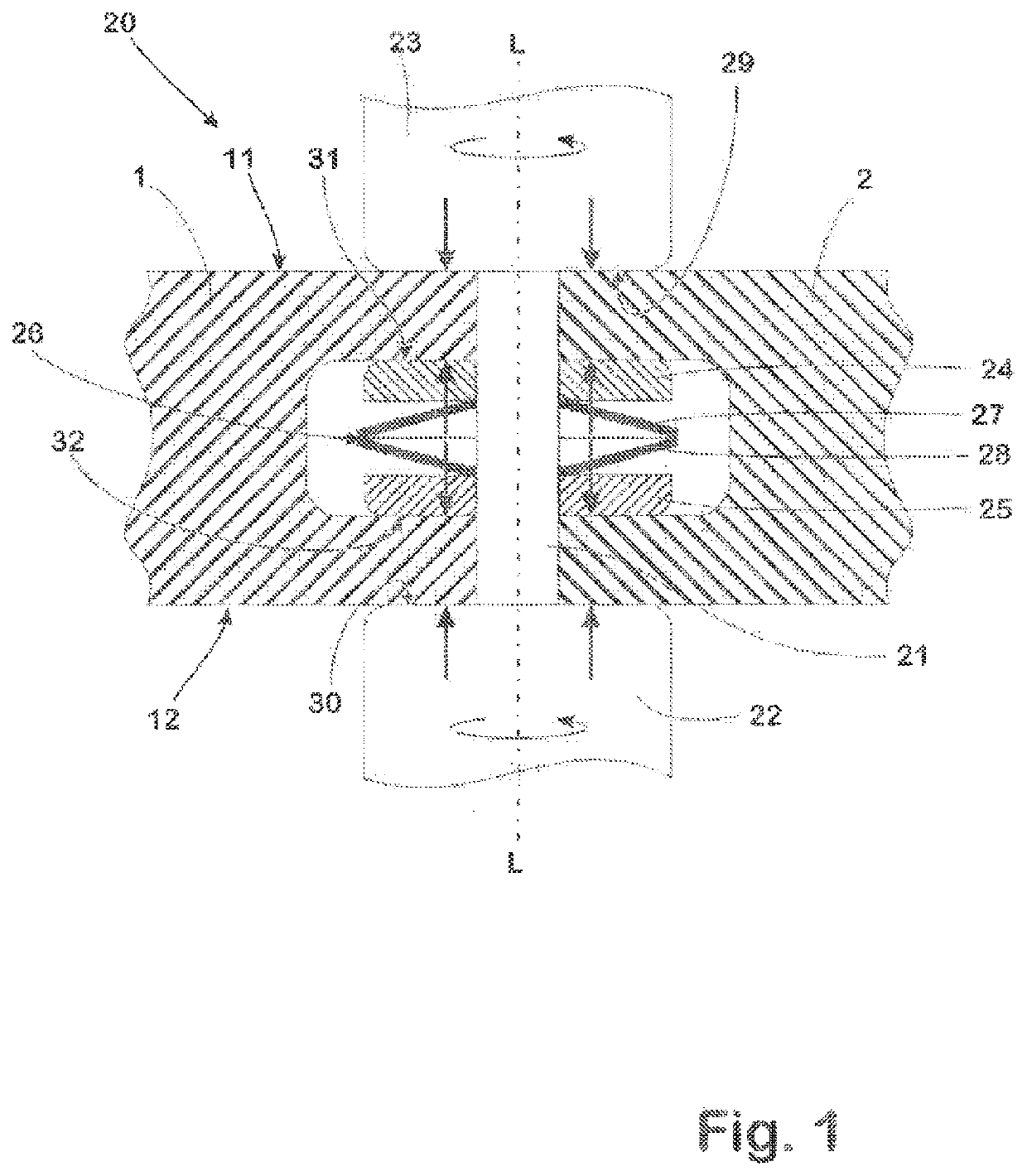
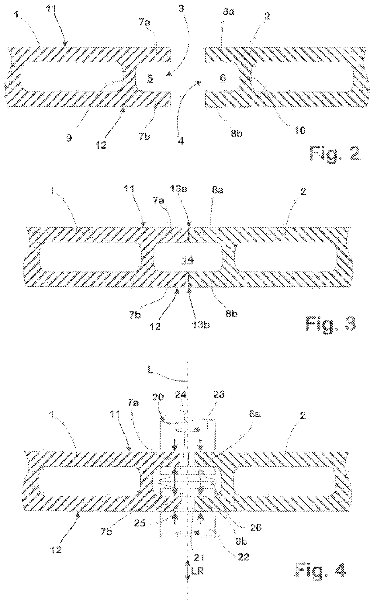
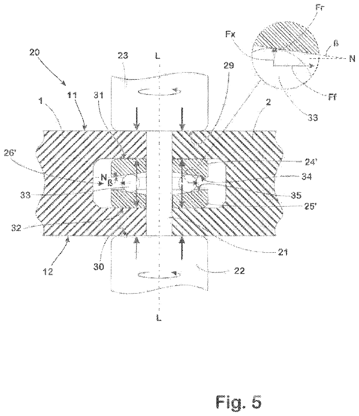
[0046]The panel elements 1, 2 are pre-fabricated in a conventional manner, for example by means of extrusion, as hollow-chamber profiles, from an aluminum material known for this purpose from the state of the art. Channel-like recesses 5, 6 are formed in the side surfaces of their longitudinal sides 3, 4, in each instance, which recesses extend over the length of the longitudinal side 3, 4 in question, and are delimited, in the case of the horizontal orientation selected in the figures, on their top side and lower side, in each instance, by a material section 7a, 7b, 8a, 8b of the corresponding panel element 1, 2. In this regard, the base of the channel-like recesses 5, 6 is formed by a crosspiece 9, 10, in each instance, of the corresponding panel element 1, 2, of the side surfaces assigned to the corresponding longitudinal side 3, 4, so that the recesses 5, 6 have a U-shaped cross-sectional shape.

[0047]For welding, the panel elements 1, 2 are butt-joined (FIG. 3), in that their lo...


PUM

PropertyMeasurementUnit
Forceaaaaaaaaaa
Distanceaaaaaaaaaa
Stress optical coefficientaaaaaaaaaa

Abstract

The invention makes available a tool for friction stir welding, which makes it possible, with reduced effort, to connect two panel elements that butt up against one another with one another by means of friction stir welding, in the case of which a tunnel is formed in the region of the abutting side surfaces, by means of recesses formed in the manner of a channel in the side surfaces in question. For this purpose, the tool has a central axle configured in the manner of a pin, provided for coupling to a drive device, a first friction shoulder carried by the central axle, a second friction shoulder carried by the central axle at a distance from the first friction shoulder in the longitudinal direction of the central axle, two support shoulders carried by the central axle, arranged between the friction shoulders, one of which is mounted on the central axle in an axially displaceable manner, and an elastic element that is arranged between the support shoulders, and exerts an elastic force the axially displaceable support shoulder, which force is directed to the friction shoulder most closely adjacent, in each instance, to the axially displaceable support shoulder in the direction. According to the invention, the setting device includes a setting element that is driven outward, away from the central axle of the tool, in the radial direction, during use, by means of the centrifugal forces that are then in effect, and, during this process, acts against a slanted surface formed on the support shoulder, in each instance.

Description

CROSS-REFERENCE TO RELATED APPLICATIONS[0001]This application is the United States national phase of International Application No. PCT / IB2020 / 051252 filed Feb. 14, 2020, and claims priority to German Patent Application No. 10 2019 104 134.1 filed Feb. 19, 2019, the disclosures of which are hereby incorporated by reference in their entirety.BACKGROUND OF THE INVENTIONField of the Invention[0002]The invention relates to a tool for friction stir welding, wherein the tool comprises a central axle that is configured in the manner of a pin and intended for coupling to a drive device, a first friction shoulder that is carried by the central axle, a second friction shoulder that is carried by the central axle at a distance from the first friction shoulder in the longitudinal direction of the central axle, two support shoulders carried by the central axle, which shoulders are arranged between the friction shoulders, and at least one of which is mounted on the central axle in an axially displ...

Claims


Application Information

Patent Timeline
IPC IPC(8): B23K20/12
CPCB23K20/1225B23K2101/045B23K20/126B23K20/12
Inventor SCHUEDDEKOPF, SVEN
Owner NEMAK S A B DE
Why Eureka
Try Eureka